English
 Espaol
 Franais
 阿拉伯
阿拉伯 中文(簡)
中文(簡) Deutsch
 Italiano
 Português
 日本
日本 韓國
韓國 български
 hrvatski
 esky
esky Dansk
Dansk Nederlands
 suomi
suomi Ελληνικ
 印度
印度 norsk
norsk Polski
 Roman
Roman русский
 Svenska
英國帕金斯2506電噴柴油發(fā)動機維修保養(yǎng)故障代碼排除查詢
英國帕金斯2506電噴柴油發(fā)動機維修保養(yǎng)故障排除
2506- 15
Industrial
Engine
![]()
![]() Important Safety
Important Safety
Information
Most accidents that involve product operation, maintenance and repair are caused by failure to
observe basic safety rules or precautions. An accident can often be avoided by recognizing potentially
hazardous situations before an accident occurs. A person must be alert to potential hazards. This
person should also have the necessary training, skills and tools to perform these functions properly.
Improper operation, lubrication, maintenance or repair of this product can be dangerous and
could result in injury or death.
Do not operate or perform any lubrication, maintenance or repair on this product, until you have
read and understood the operation, lubrication, maintenance and repair information.
Safety precautions and warnings are provided in this manual and on the product. If these hazard
warnings are not heeded, bodily injury or death could occur to you or to other persons.
The hazards are identified by the “Safety Alert Symbol” and followed by a “Signal Word” such as
“DANGER”, “WARNING” or “CAUTION”. The Safety Alert “WARNING” label is shown below.
The meaning of this safety alert symbol is as follows:
Attention! Become Alert! Your Safety is Involved.
The message that appears under the warning explains the hazard and can be either written or
pictorially presented.
Operations that may cause product damage are identified by “NOTICE” labels on the product and in
this publication.
Perkins cannot anticipate every possible circumstance that might involve a potential hazard. The
warnings in this publication and on the product are, therefore, not all inclusive. If a tool, procedure,
work method or operating technique that is not specifically recommended by Perkins is used,
you must satisfy yourself that it is safe for you and for others. You should also ensure that the
product will not be damaged or be made unsafe by the operation, lubrication, maintenance or
repair procedures that you choose.
The information, specifications, and illustrations in this publication are on the basis of information that
was available at the time that the publication was written. The specifications, torques, pressures,
measurements, adjustments, illustrations, and other items can change at any time. These changes can
affect the service that is given to the product. Obtain the complete and most current information before
you start any job. Perkins dealers or Perkins distributors have the most current information available.
When
replacement
parts
are
required
for
this
product Perkins recommends using Perkins
replacement parts.
Failure to heed this warning can lead to prema-
ture failures, product damage, personal injury or
death.
![]() KENR6224
KENR6224
3
Table of Contents
Table
of
Contents
CID 0003 FMI 11 ................................................... 55
CID 0004 FMI 11 ................................................... 55
CID 0005 FMI 11 ................................................... 56
CID 0006 FMI 11 ................................................... 56
Troubleshoot ing Section
Electronic Troubleshooting
System Overview .................................................... 5
Glossary .................................................................. 7
Electronic Service Tools ........................................ 10
Replacing the ECM ............................................... 12
Self-Diagnostics .................................................... 13
Sensors and Electrical Connectors ....................... 14
Engine Wiring Information .................................... 18
Programming Parameters
Programming Parameters ..................................... 21
Factory Passwords ............................................... 21
Factory Passwords Worksheet ............................. 21
Flash Programming .............................................. 22
Injector Trim File ................................................... 23
System Configuration Parameters
System Configuration Parameters ........................ 24
Troubleshooting without a Diagnostic Code
Alternator Noise .................................................... 31
Alternator Will Not Charge .................................... 31
Battery .................................................................. 31
Can Not Reach Top Engine RPM ......................... 32
Coolant in Engine Oil ............................................ 33
Coolant Temperature Is Too High ......................... 34
ECM Will Not Accept Factory Passwords ............. 34
ECM Will Not Communicate with Other Systems or
Display Modules .................................................. 34
Electronic Service Tool Will Not Communicate with
ECM .................................................................... 35
Engine Cranks but Will Not Start .......................... 36
Engine Has Early Wear ........................................ 37
Engine Misfires, Runs Rough or Is Unstable ........ 38
Engine Oil in Cooling System ............................... 39
Engine Vibration ................................................... 39
Engine Will Not Crank ........................................... 40
Excessive Black Smoke ........................................ 40
Excessive Engine Oil Consumption ...................... 41
Excessive Fuel Consumption ............................... 42
Excessive Valve Lash ........................................... 43
Excessive White Smoke ....................................... 43
Fuel Dilution of Engine Oil .................................... 44
Intermittent Engine Shutdown ............................... 45
Low Engine Oil Pressure ...................................... 46
Low Power ............................................................ 46
Mechanical Noise (Knock) in Engine .................... 47
Noise Coming from Cylinder ................................. 48
Poor Acceleration or Response ............................ 49
Valve Rotator or Spring Lock Is Free .................... 50
Troubleshooting with a Diagnostic Code
Flash Codes .......................................................... 51
Diagnostic Codes .................................................. 51
Diagnostic Code Cross Reference ....................... 52
CID 0001 FMI 11 ................................................... 54
CID 0002 FMI 11 ................................................... 55
CID 0041 FMI 03 .................................................. 56
CID 0041 FMI 04 .................................................. 57
CID 0091 FMI 08 .................................................. 57
CID 0100 FMI 03 .................................................. 57
CID 0100 FMI 04 .................................................. 57
CID 0110 FMI 03 ................................................... 58
CID 0110 FMI 04 ................................................... 58
CID 0168 FMI 02 .................................................. 58
CID 0172 FMI 03 .................................................. 59
CID 0172 FMI 04 .................................................. 59
CID 0174 FMI 03 .................................................. 59
CID 0174 FMI 04 .................................................. 59
CID 0190 FMI 02 .................................................. 60
CID 0190 FMI 09 .................................................. 60
CID 0190 FMI 11 ................................................... 60
CID 0190 FMI 12 .................................................. 61
CID 0247 FMI 09 .................................................. 61
CID 0248 FMI 09 .................................................. 61
CID 0253 FMI 02 .................................................. 61
CID 0254 FMI 12 .................................................. 62
CID 0261 FMI 13 .................................................. 62
CID 0262 FMI 03 .................................................. 62
CID 0262 FMI 04 .................................................. 63
CID 0268 FMI 02 .................................................. 63
CID 0273 FMI 03 .................................................. 63
CID 0273 FMI 04 .................................................. 63
CID 0274 FMI 03 .................................................. 64
CID 0274 FMI 04 .................................................. 64
CID 0342 FMI 02 .................................................. 64
CID 0342 FMI 11 ................................................... 65
CID 0342 FMI 12 .................................................. 65
CID 0799 FMI 12 .................................................. 65
CID 1690 FMI 08 .................................................. 66
Troubleshooting with an Event Code
Event Codes ........................................................ 67
E162 High Boost Pressure ................................... 69
E360 Low Engine Oil Pressure ............................. 70
E361 High Engine Coolant Temperature .............. 71
E362 Engine Overspeed ....................................... 72
E363 High Fuel Supply Temperature .................... 72
E368 High Intake Manifold Air Temperature ......... 73
Diagnostic Functional Tests
5 Volt Engine Pressure Sensor Supply Circuit -
Test ..................................................................... 75
CAN Data Link Circuit - Test ................................. 81
Data Link Circuit - Test .......................................... 85
ECM Memory - Test .............................................. 88
Electrical Connectors - Inspect ............................. 90
Electrical Power Supply Circuit - Test ................... 94
Engine Pressure Sensor Open or Short Circuit -
Test ..................................................................... 97
Engine Speed/Timing Sensor Circuit - Test ........ 103
Engine Temperature Sensor Open or Short Circuit -
Test .................................................................... 110
Indicator Lamp Circuit - Test ................................ 115
Injector Solenoid Circuit - Test ............................. 119
Speed Control (Analog) - Test ............................ 126
![]() 4
4
Table of Contents
KENR6224
Speed Control (PWM) - Test ............................... 129
Switch Circuits - Test .......................................... 134
Calibration Procedures
Engine Speed/Timing Sensor - Calibrate ............ 138
Index Section
Index ................................................................... 140
![]()
![]() KENR6224
KENR6224
5
Troubleshooting Section
Troubleshoot ing
Section
Ele ct ron ic
Trou bl es hoot ing
System Overview
i02547521
System Operation
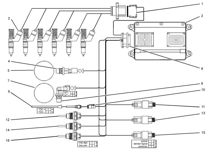
Illustration 1
Block diagram for the 2506-15 engine
(1) 12 Pin Connector
(2) Electronic Control Module (ECM)
(3) Electronic Unit Injectors
(4) Crankshaft Position Sensor
(5) 36 - 1 Tooth Gear
(6) 120 Pin Connector
(7) 36 + 1 Tooth Gear
(8) Camshaft Position Sensor
(9) Timing Calibration Probe
(10) Timing Calibration Probe Connector
(11) Atmospheric Pressure Sensor
(12) Inlet Manifold Temperature Sensor
g01277565
(13) Inlet Manifold Pressure Sensor
(14) Coolant Temperature Sensor
(15) Engine Oil Pressure Sensor
(16) Fuel Temperature Sensor
This engine is electronically controlled. Each cylinder
has an electronic unit injector. The Electronic Control
Module (ECM) sends a signal to each injector
solenoid in order to control the operation of the fuel
injection system.
![]() 6
6
Troubleshooting Section
KENR6224
Electronic Cont rols
The electronic system consists of the following
components: the ECM, the Mechanically Actuated
Electronically Controlled Unit Injectors (MEUI), the
wiring harness, the switches, and the sensors. The
ECM is the computer. The flash file is the software
for the computer. The flash file contains the operating
maps. The operating maps define the following
characteristics of the engine:
• Horsepower
• Torque curves
The ECM determines the timing and the amount of
fuel that is delivered to the cy linders. These decisions
are based on the ac tual conditions and/or on the
desired conditions at any given time.
The ECM compares the desired engine speed to
the actual engine speed. The actual engine speed is
determined through the engine speed/timing sensor.
The desired engine speed is determined with the
following factors:
• Throttle signal
• Other input signals from sensors
• Certain diagnostic codes
If the desired engine speed is greater than the actual
engine speed, the ECM injects more fuel in order to
increase the actual engine speed.
Fuel Injection
The ECM controls the amount of fuel that is injected
by varying the signals to the injectors. The injector will
pump fuel only if the injector solenoid is energized.
The ECM sends a high voltage signal to the solenoid.
This high voltage signal energizes the solenoid. By
controlling the timing and the duration of the high
voltage signal, the ECM can c ontrol injection timing
and the ECM can control the amount of fuel that is
injected.
The ECM limits engine power during cold mode
operation and the ECM modifies injection timing
during cold mode operation. Cold mode operation
provides the following benefits:
• Increased cold weather starting capability
• Reduced warm-up time
• Reduced white smoke
Cold mode is activated whenever the engine
temperature falls below a predetermined value. Cold
mode remains active until the engine temperature
rises above a predetermined value or until a time
limit is exceeded.
The flash file inside the ECM sets certain limits on
the amount of fuel that can be injected. The “FRC
Fuel Limit” is used to control the air/fuel ratio for
control of emissions. The “FRC Fuel Limit” is a limit
that is based on the turbocharger outlet pressure.
A higher turbocharger outlet pressure indicates that
there is more air in the cylinder. When the ECM
senses a higher turbocharger outlet pressure, the
ECM increases the “FRC Fuel Limit”. When the ECM
increases the “FRC Fuel Limit”, the ECM allows
more fuel into the cylinder. The “FRC Fuel Limit” is
programmed into the ECM at the factory. The “FRC
Fuel Limit” cannot be changed.
The “Rated Fuel Limit” is a limit that is based on the
power rating of the engine and on engine rpm. The
“Rated Fuel Limit” is similar to the rack stops and to
the torque spring on a mechanically governed engine.
The “Rated Fuel Limit” provides the power curves
and the torque curves for a specific engine family and
for a spec ific engine rating. The “Rated Fuel Limit” is
programmed into the ECM at the factory. The “Rated
Fuel Limit” cannot be changed.
Once the ECM determines the amount of fuel that
is required, the ECM must determine the timing of
the fuel injection. The ECM uses the signal from the
camshaft position sensor to c alculate the top center
pos ition of eac h cylinder . The ECM decides when
fuel injection should occur relative to the top center
pos ition and the ECM provides the signal to the
injector at the desired time. The ECM adjusts timing
for optimum engine performance, for optimum fuel
economy, and for optimum control of white smoke.
Programmable Parameters
Certain parameters that affect the engine operation
may be changed with the Perkins Electronic
Service Tool (EST). The parameters are stored
in the ECM, and some parameters are protected
from unauthorized changes by passwords. These
pas swords are c alled factory passwords.
Passwords
Several system configuration parameters and most
logged events are protected by factory passwords .
Factory passwords are available only to Perkins
dealers and distributors. Refer to Troubleshooting,
“Factory Passwords” for additional information.
![]() KENR6224
KENR6224
7
Troubleshooting Section
i02554801
Crankshaft Position Sensor
– This sensor
Glossary
Active Diagnostic Code
– An active diagnostic
determines the position of the crankshaft during
engine operation. If the crankshaft position sensor
fails during engine operation, the camshaft position
sensor is used to provide the signal.
Data Link – The Data Link is a serial communication
code alerts the operator or the service technician that
an electronic system malfunction is currently present.
Refer to the term “Diagnostic Code” in this glossary.
Adaptive Trim – This is a software process that is
performed in the Electronic Control Module (ECM)
that optimizes engine performance.
Alternating Current (AC) – Alternating current is an
electric current that reverses direction at a regular
interval that is reoccurring.
Before Top Center (BTC) – BTC is the 180 degrees
of crankshaft rotation before the piston reaches the
top dead center position in the normal direction of
rotation.
Breakout Harness – A breakout harness is a
test harness that is designed to connect into the
engine harness. This connection allows a normal
circuit operation and the connection simultaneously
provides a Breakout T in order to measure the
signals.
Bypass Circuit – A bypass circuit is a circuit that is
used as a substitute circuit for an existing circuit. A
bypass circ uit is typically used as a test circuit.
Camshaft Position Sensor – This sensor
determines the position of the camshaft during
engine operation. If the crankshaft position sensor
fails during engine operation, the camshaft position
sensor is used to provide the signal.
CAN Data Link (see also J1939 CAN Data Link) –
The CAN Data Link is a serial communications
port that is used for communication with other
microprocessor based devices.
Code – Refer to “Diagnostic Code” or “Event Code”.
Communication Adapter Tool – The
communication adapter provides a communication
link between the ECM and the electronic service tool.
Component Identifier (CID) – The CID is a number
that identifies the specific component of the electronic
control system that has experienced a diagnostic
code.
Coolant Temperature Sensor – The coolant
temperature sensor detects the engine coolant
temperature for all normal operating conditions and
for engine monitoring.
port that is used for communication with other devices
such as the electronic service tool.
Derate – Certain engine conditions will generate
event codes. Also, engine derates may be applied.
The map for the engine derate is programmed into
the ECM software. The derate can be one or more of
3 types: reduction of rated power, reduction of rated
engine speed, and reduction of rated machine speed
for OEM products.
Desired Engine Speed – The desired engine speed
is input to the electronic governor within the ECM.
The electronic governor uses the signal from the
throttle position sensor, the engine speed/timing
sensor, and other sensors in order to determine the
desired engine speed.
Diagnostic Code – A diagnostic code is sometimes
referred to as a fault code. These codes indicate an
electronic system malfunction.
Diagnostic Lamp – A diagnostic lamp is sometimes
called the check engine light. The diagnostic lamp
is used to warn the operator of the presence of
an active diagnostic code. The lamp may not be
included in all applications.
Digital Sensor Return – The common line (ground)
from the ECM is used as ground for the digital
sensors.
Digital Sensors – Digital sensors produce a pulse
width modulated signal. Digital sensors are supplied
with power from the ECM.
Digital Sensor Supply – The power supply for the
digital s ensors is provided by the ECM.
Direct Current (DC) – Direct current is the type of
current that flows consistently in only one direction.
DT, DT Connector, or Deutsch DT – This is a type
of connector that is used on Perkins engines. The
connectors are manufactured by Deutsch.
Duty Cycle – Refer to “Pulse Width Modulation”.
Electronic Engine Control – The electronic
engine control is a complete electronic system.
The electronic engine control monitors the engine
operation under all conditions. The electronic engine
control also controls the engine operation under all
conditions.
![]() 8
8
Troubleshooting Section
KENR6224
Electronic Control Module (ECM) – The ECM
7
– The mechanic al system is not responding
is the control computer of the engine. The ECM
provides power to the electronics. The ECM monitors
data that is input from the sensors of the engine. The
ECM acts as a governor in order to control the speed
and the power of the engine.
Electronic Service Tool – The electronic service
tool allows a computer (PC) to communicate with the
ECM.
Engine Monitoring – Engine Monitoring is the part
of the electronic engine control that monitors the
sensors. This also warns the operator of detected
faults.
Engine Oil Pressure Sensor – The engine oil
pressure sensor measures engine oil pressure. The
sensor sends a signal to the ECM that is dependent
on the engine oil pressure.
Engine Position Sensor – An engine position
sensor is a hall effect switc h that provides a digital
signal to the ECM. The ECM interprets this signal as
the crankshaft position and the engine speed. Two
sensors are used to provide the speed and timing
signals to the ECM. The crankshaft position sensor
is associated with the crankshaft and the camshaft
position sensor is associated with the camshaft.
Event Code – An event code may be activated
in order to indicate an abnormal engine operating
condition. These codes usually indicate a mechanical
fault instead of an electrical system fault.
Failure Mode Identifier (FMI) – This identifier
indicates the type of failure that is associated with
the component. The FMI has been adopted from the
SAE practice of J1587 diagnostics. The FMI follows
the parameter identifier (PID) in the descriptions of
the fault code. The descriptions of the FMIs are in
the following list.
0 – The data is valid but the data is above the normal
operational range.
1 – The data is valid but the data is below the normal
operational range.
2 – The data is erratic, intermittent, or incorrect.
3 – The voltage is above normal or the voltage is
shorted high.
4 – The voltage is below normal or the voltage is
shorted low.
5 – The current is below normal or the circuit is open.
6 – The current is above normal or the circuit is
grounded.
properly.
8 – There is an abnormal frequency, an abnormal
pulse width, or an abnormal time period.
9 – There has been an abnormal update.
10 – There is an abnormal rate of change.
11 – The failure mode is not identifiable.
12 – The device or the component is damaged.
Flash File – This file is software that is inside
the ECM. The file contains all the instructions
(software) for the ECM and the file contains the
performance maps for a specific engine. The file may
be reprogrammed through flash programming.
Flash Programming – Flash programming is the
method of programming or updating an ECM with
an electronic servic e tool over the data link instead
of replacing components.
Fuel Injector E-Trim – Fuel injector E-trim is a
software process that allows precise control of fuel
injectors by parameters that are programmed into
the ECM for eac h fuel injector. With the use of the
electronic service tool, the service technician can
read status information for the E-Trim. Data for
E-Trim can also be programmed.
FRC – See “Fuel Ratio Control”.
Fuel Ratio Control (FRC) – The FRC is a limit that
is based on the control of the ratio of the fuel to air.
The FRC is used for purposes of emission control.
When the ECM senses a higher intake manifold
air pressure (more air into the cylinder), the FRC
increases the FRC Limit (more fuel into the cylinder).
Full Load Setting (FLS) – The FLS is the parameter
that represents the fuel system adjustment. This
adjustment is made at the factory in order to fine tune
the fuel system. The correct value for this parameter
is stamped on the engine information ratings plate.
This parameter must be programmed.
Full Torque Setting (FTS) – The FTS is the
parameter that represents the adjustment for the
engine torque. This adjustment is made at the factory
in order to fine tune the fuel system. This adjustment
is made in conjunction with the FLS. This parameter
must be programmed.
Harness – The harness is the bundle of wiring
(loom) that connects all components of the electronic
system.
![]()
![]() KENR6224
KENR6224
9
Troubleshooting Section
Hertz (Hz)
– Hertz is the measure of electrical
Password – A password is a group of numeric
frequency in cycles per second.
Injector Codes – The injector codes or injector trim
codes are numeric codes or alphanumeric codes
that are etched or stamped on individual electronic
unit injectors. These codes are used to fine tune the
fuel delivery.
Injector Trim Files – Injector trim files are
downloaded from a disk to the ECM. The injector
trim files compensate for variances in manufacturing
of the electronic unit injector and for the life of the
electronic unit injector. The serial number for the
electronic unit injector must be obtained in order to
retrieve the correct injector trim file.
Intake Manifold Air Temperature Sensor – The
intake manifold air temperature sensor detec ts the
air temperature in the intake manifold. The ECM
monitors the air temperature and other data in the
intake manifold in order to adjust injection timing and
other performance functions .
Intake Manifold Pressure Sensor – The Intak e
Manifold Pressure Sensor measures the pressure
in the intake manifold. The pressure in the intake
manifold may be different to the pressure outside
the engine (atmospheric pressure). The difference
in pressure may be caused by an increase in air
pressure by a turbocharger (if equipped).
Integrated Electronic Controls – The engine is
designed with the electronic controls as a necessary
part of the system. The engine will not operate
without the electronic controls.
J1939 CAN Data Link – This data link is a SAE
standard diagnostic c ommunications data link that
is used to communicate between the ECM and the
electronic dev ices.
Logged Diagnostic Codes – Logged diagnostic
codes are codes which are stored in the memory.
These codes are meant to be an indicator of
possible causes for intermittent faults. Refer to the
term “Diagnostic Code” in this glossary for more
information.
OEM – OEM is an abbreviation for the Original
Equipment Manufacturer. This is the manufacturer of
the machine or the vehicle that uses the engine.
Open Circuit – An open circuit is a condition that is
caused by an open switch, or by an elec trical wire
or a connection that is broken. When this condition
exists, the signal or the supply voltage can no longer
reach the intended destination.
Parameter – A parameter is a value or a limit that
is programmable. This helps determine specific
characteristics or behaviors of the engine.
|
that is designed to restrict acc ess to parameters. The
electronic system requires correct passwords in order
to change some parameters (Factory Passwords).
Refer to Troubleshooting, “Factory Passwords” for
more information.
Personality Module – See “Flash File”.
Power Cycled – Power cycled happens when power
to the ECM is cycled: ON, OFF, and ON. Power
cycled refers to the action of cycling the k eyswitch
from any position to the OFF position, and to the
START/RUN position.
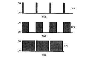
Pulse Width Modulation (PWM) – The PWM is a
signal that consists of pulses that are of variable
width. These pulses occur at fixed intervals. The ratio
of “TIME ON” versus total “TIME OFF” c an be varied.
This ratio is also referred to as a duty cycle.
Illustration 2
Rated Fuel Limit – This is a limit that is based on
the power rating of the engine and on the engine rpm.
The Rated Fuel Limit enables the engine power and
torque outputs to conform to the power and torque
curves of a specific engine model. These limits are in
the flash file and these limits cannot be changed.
Reference Voltage – Reference voltage is a
regulated voltage and a steady voltage that is
supplied by the ECM to a sensor. The reference
voltage is used by the sensor to generate a signal
voltage.
Relay – A relay is an electromec hanical switc h. A
flow of electricity in one circuit is used to control the
flow of electricity in another circuit. A small current or
voltage is applied to a relay in order to switch a much
larger current or voltage.
Sensor – A sens or is a device that is used to
detect the current value of pressure or temperature,
or mechanical movement. The information that is
detected is converted into an electrical signal.
| |||||||||||||||||||||||||||
Troubleshooting Section
KENR6224
Short Circuit – A short circuit is a condition that has
an electrical circuit that is inadvertently connected to
an undesirable point. An example of a short circuit
is a wire which rubs against a vehicle frame and
this rubbing eventually wears off the wire insulation.
Electrical contact with the frame is made and a s hort
circuit results.
Signal – The signal is a voltage or a waveform that
is used in order to transmit information ty pically from
a sensor to the ECM.
•
•
•
•
•
Obtain data.
Diagnose faults.
Read parameters.
Program parameters.
Calibrate sensors.
Supply Voltage – The supply voltage is a continuous
voltage that is supplied to a component in order to
provide the elec trical power that is required for the
component to operate. The power may be generated
by the ECM or the power may be battery voltage that
is supplied by the engine wiring.
System Configuration Parameters – System
configuration parameters are parameters that affect
emiss ions and/or operating charac teristics of the
engine.
Tattletale – Certain parameters that affect the
operation of the engine are stored in the ECM.
These parameters can be changed by use of the
electronic service tool. The tattletale logs the number
of changes that have been made to the parameter.
The tattletale is stored in the ECM.
Throttle Position – The throttle position is the
interpretation by the ECM of the signal from the
throttle position sensor or the throttle switch.
Timing Calibration – The timing calibration is the
adjustment of an electrical signal. This adjustment is
made in order to correct the timing error between the
camshaft and the engine speed/timing sensors or
between the crankshaft and the engine speed/timing
sensors.
Top Center Position – The top center position refers
to the crankshaft position when the engine piston
position is at the highest point of travel. The engine
must be turned in the normal direction of rotation in
order to reach this point.
Total Tattletale – The total tattletale is the total
number of changes to all the parameters that are
stored in the ECM.
i02547729
Electronic Service Tools
Perkins Electronic Service Tools are designed to help
the service technician:
Required Service Tools
The tools that are listed in Table 1 are required in
order to enable a service technician to perform the
procedures.
Table 1
Two short jumper wires are needed to check the
continuity of some wiring harness circuits by shorting
two adjacent terminals together in a connector. A
long extension wire may also be needed to check the
continuity of some wiring harness circuits.
Perkins Electronic Service Tool
(EST)
The Perkins EST can display the following
information:
• Parameters
• Event codes
• Diagnostic codes
• Engine configuration
![]()
![]()
![]() KENR6224
KENR6224
11
Troubleshooting Section
The Perkins EST can be used by the technician to
perform the following functions:
• Diagnostic tests
• Sensor calibration
• Flash programming
• Set parameters
Table 2 lists the service tools that are required in
order to use Perkins EST.
Table 2
Connecting Perkins EST and the
Communication Adapter II
|
Service Tools for the Use of Perkins EST | |
|
Part Number |
Description |
|
-(1) |
Personal Computer (PC) |
|
-(1) |
Single user license for Perkins EST |
|
-(1) |
Data Subscription for All Engines |
|
27610251 |
Communi cation Adapter Gp |
|
27610164(2) |
Adapter Cable As |
(1)
(2)
Refer to the Perkins Engine Company Limited.
The 27610164 Adapter Cable As is required to connect to the
USB port on computers that are not equipped with a RS232
serial port.
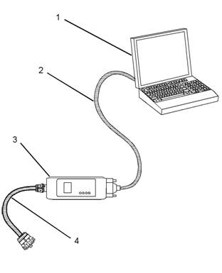
Illustration 3
(1) Personal computer (PC)
g01115382
Note: For more information regarding the use of
Perkins EST and the PC requirements for Perkins
EST, refer to the documentation that accompanies
your Perkins EST software.
(2) Adapter Cable (RS232 Port)
(3) Communication Adapter As
(4) Adapter Cable As
Note: Items (2), (3), and (4) are part of the 27610251
Communication Adapter Gp.
Use the following procedure in order to c onnect
Perkins EST and the Communication Adapter II.
1. Turn the keyswitch to the OFF position. If the
keyswitch is not in the OFF position, the engine
may start.
2. Connect cable (2) between the “COMPUTER”
end of communication adapter (3) and the RS232
serial port of PC (1).
Note: An adapter cable assembly is required to
connect to the USB port on computers that are not
equipped with a RS232 serial port.
3. Connect cable (4) between the “DATA LINK” end
of communication adapter (3) and the diagnostic
connector.
![]()
![]()
![]() 12
12
Troubleshooting Section
KENR6224
4.
Place the keyswitch in the ON position. If the
Perkins EST and the communication adapter
do not communicate with the Elec tronic Control
Module (ECM), refer to the diagnostic procedure
Troubleshooting, “Electronic Service Tool Will Not
Communicate With ECM”.
i02548810
1.
Rec ord the configuration data:
a. Connec t the electronic service tool to the
diagnostic connector. Refer to Troubleshooting,
“Electronic Service Tools”.
b. Print the parameters from the “Configuration”
screen on the electronic service tool. If a printer
is unavailable, record all of the parameters.
Record any logged diagnos tic codes and
Replacing
the
ECM
logged event codes for your records. Record
the injector codes from the “Calibrations”
screen in the “Service” menu on the electronic
service tool.
NOTICE
Keep all parts clean from contaminants.
c.
Use the “Copy
Configuration/ECM
Contaminants may cause rapid wear and shortened
component life.
The Electronic Control Module (ECM) contains no
moving parts. Replacement of the ECM can be
costly. Replacement can also be a time consuming
task. Follow the troubleshooting procedures in this
manual in order to ensure that replacing the ECM will
correct the fault. Verify that the suspect ECM is the
cause of the fault.
Note: Ensure that the ECM is receiving power and
that the ECM is properly wired to the negative battery
circuit before a replacement of the ECM is attempted.
Refer to Troubleshooting, “Electrical Power Supply
Circuit - Test”.
A test ECM can be used to determine if the ECM is
faulty. Install a test ECM in place of the suspect ECM.
Flash program the correct flash file into the test ECM.
Program the parameters for normal operation of the
engine. The parameters must match the parameters
in the suspect ECM. Refer to the following test steps
for details. If the test ECM resolves the fault, connect
the suspect ECM. Verify that the fault returns. If the
fault returns, replace the suspect ECM.
Note: When a new ECM is not available, you may
need to remove an ECM from an engine that is not
in service. The interlock code for the replacement
ECM mus t match the interlock code for the suspect
ECM. Be sure to record the parameters from the
replacement ECM on the “Parameters Worksheet”.
Use the “Copy Configuration/ECM Replacement”
feature that is found under the “Service” menu on
the electronic service tool.
NOTICE
If the flash file and engine application are not matched,
engine damage may result.
Perform the following procedure in order to replace
the ECM:
Replacement” feature that is found under the
“Service” menu on the electronic serv ice tool.
Select “Load from ECM” in order to copy the
configuration data from the suspect ECM.
Note: If the “Copy Configuration” process fails and
the parameters were not obtained in Step 1.b, the
parameters must be obtained elsewhere. Some of the
parameters are stamped on the engine information
plate. Most of the parameters must be obtained from
the factory.
2. Remove the ECM:
a. Turn the keyswitch to the OFF position.
b. Disconnect the P1 and P2 connectors from
the ECM.
c. Disconnect the ECM ground s trap.
d. Remove the mounting bolts from the ECM.
3. Install the replacement ECM:
a. Use the old mounting hardware to install the
replacement ECM.
b. Connec t the ECM ground strap.
c. Connec t the P1 and P2 connectors. Tighten
the ECM connector (allen head screw) to
the proper torque. Refer to Troubleshooting,
“Electrical Connectors - Inspect” for the correct
torque value.
4. Configure the replacement ECM:
a. Flash program the flash file into the ECM.
Refer to Troubleshooting, “Flash Programming”
for the correct procedure.
![]() KE, NR6224
KE, NR6224
13
Troubleshooting Section
b. Use the electronic service tool to match the
engine application and the interlock code if
the replacement ECM was used for a different
application.
c. If the “Copy Configuration” process from
Step 1.b was successful, return to the “Copy
Configuration/ECM Replacement” screen on
the electronic service tool and select “Program
ECM”. Proceed to Step 4.e when programming
is c omplete.
d. If the “Copy Configuration” process from Step
1.b was unsuccessful, manually program the
ECM parameters. The parameters must match
the parameters from Step 1.b.
e. Program the engine monitoring system, if
necessary.
f. Load the injector trim files for the injectors.
Refer to Troubleshooting, “Injector Trim File”.
g. Calibrate the engine speed/timing. Refer
to Troubleshooting, “Engine Speed/Timing
Sensor - Calibrate”.
Every generated code is stored in the permanent
memory of the ECM. The codes are logged.
Logged codes may not indicate that a repair is
needed. The fault may have been temporary. The
fault may have been resolved since the logging of
the code. If the system is powered, it is possible
to generate an active diagnostic code whenever a
component is disconnected. When the component is
reconnected, the code is no longer active. Logged
codes may be useful to help troubleshoot intermittent
faults. Logged codes can also be used to review
the performance of the engine and of the electronic
system.
Event Code
An event code is generated by the detection of an
abnormal engine operating condition. For example,
an event code will be generated if the oil pressure is
too low. In this case, the event c ode indicates the
symptom of a fault.
Self-Diagnostics
i02548823
The Electronic Control Module (ECM) has the ability
to detect faults with the electronic sys tem and with
engine operation. When a fault is detected, a code is
generated. An alarm may also be generated. There
are two types of codes:
• Diagnostic
• Event
Diagnostic Code – When a fault with the electronic
system is detected, the ECM generates a diagnostic
code. This indicates the specific fault with the
circuitry.
Diagnostic codes can have two different states:
• Active
• Logged
Active Code
An active diagnostic code indicates that an active
fault has been detected. Activ e c odes require
immediate attention. Always service active codes
prior to servicing logged codes.
Logged Code
![]() 14
14
Troubleshooting Section
KENR6224
Sensors
and
Electrical
i02548835
Connectors
Table 3
|
Connector |
Function |
|
J1/P1 |
ECM Connector (70-Pin Engine Harness) |
|
J2/P2 |
ECM Connector (“120-Pi n Engine Harness”) |
|
J61/P61 |
Customer Connector (Optional) (40-Pin Connector) |
|
J63/P63 |
Diagnostic Connector (9-Pin Connector) |
|
J100/P100 |
Coolant Temperature Sensor (2-Pin Connector) |
|
J103/P103 |
Inlet Manifold Temperature Sensor (2-Pin Connector) |
|
J105/P105 |
Fuel Temperature Sensor (2-Pin Connector) |
|
J200/P200 |
Inlet Manifold Pressure Sensor (3-Pin Connector) |
|
J201/P201 |
Engine Oil Pressure Sensor (3-Pin Connector) |
|
J203/P203 |
Atmospheric Pressure Sensor (3-Pin Connector) |
|
J300/P300 |
Injector Solenoid Harness (12-Pin Connector) |
|
J400/P400 |
Engine Timing Cal ibr ation Probe (2-Pin Connector) |
|
J401/P401 |
Crankshaft Position Sensor (2-Pin Connector) |
|
J402/P402 |
Camshaft Position Sensor (2-Pin Connector) |
![]()
![]()
![]() KENR6224
KENR6224
15
Troubleshooting Section
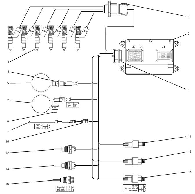
Illustration 4
Block diagram for the 2506-15 engine components
(1) 12 Pin Connector (9) Timing Calibration Probe
(2) Electronic Control Module (ECM) (10) Timing Calibration Probe Connector
(3) Electronic Unit Injectors (11) Atmospheric Pressure Sensor
(4) Crankshaft Position Sensor (12) Inlet Manifold Temperature Sensor
(5) 36 - 1 Tooth Gear (13) Inlet Manifold Pressure Sensor
(6) 120 Pin Connector (14) Coolant Temperature Sensor
(7) 36 + 1 Tooth Gear (15) Engine Oil Press ure Sensor
(8) Camshaft Position Sensor (16) Fuel Temperature Sensor
g01278058
![]()
![]()
![]() 16
16
Troubleshooting Section
KENR6224
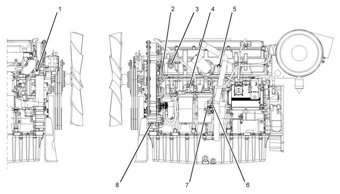
Illustration 5
Locations of the sensors on the 2506-15 engine
(1) Coolant temperature sensor
(2) Camshaft position sensor
(3) Inlet manifold pressure sensor
(4) Fuel temperature sensor
(5) Inlet manifold temperature sensor
(6) Engine oil pres sure sensor
(7) Atmospheric pressure sensor
(8) Crank shaft position sensor
g01279372
![]()
![]()
![]() KENR6224
KENR6224
17
Troubleshooting Section
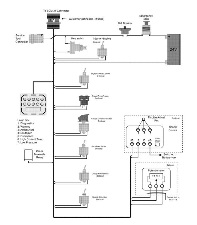
Illustration 6
Block diagram for the machine components
g01278305
| |||||||||||||||||||||||||||||||||
Troubleshooting Section
KENR6224
Engine Wiring
Information
i02548945
1.
2.
Stop the engine. Turn the keyswitch to the OFF
position.
Disconnect the negative battery cable from the
battery. If a battery disconnect switc h is installed,
open the switch.
The wiring schematics are revised periodically.
The wiring schematics will change as updates are
made to the machine harness. For the most current
information, always check the revision number of the
schematic. Use the schematic with the latest revision
number.
Harness Wire Identification
Perkins identifies all wires with eleven solid c olors.
The circuit number is stamped on the wire at a 25 mm
(1 inch) spacing. Table 4 lists the wire colors and the
color codes.
Table 4
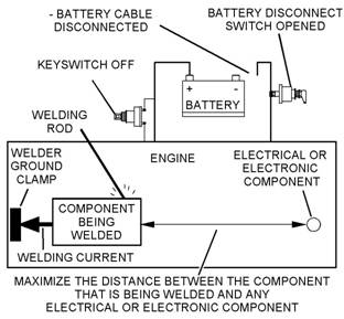
Illustration 7
Service welding guide (typical diagram)
g01143634
Welding on a Machine that is Equipped
with an Electronic Control System ( ECM)
Proper welding procedures are necessary in order
to avoid damage to the engine’s electronic c ontrol
module, sensors, and associated components. The
component that requires welding should be removed.
When welding on a machine that is equipped with an
ECM and removal of the component is not possible,
the following procedure must be followed. This
procedure provides the minimum amount of risk to
the electronic components.
NOTICE
Do not ground the welder to electrical components
such as the ECM or sensors. Improper grounding can
cause damage to the drive train bearings, hydraulic
components, electrical components, and other com-
ponents.
Clamp the ground cable from the welder to the com-
ponent that will be welded. Plac e the clamp as close
as possible to the weld. This will help reduce the pos-
sibility of damage.
3.
4.
5.
Connect the welding ground cable as close
as possible to the area that will be welded.
Components which may be damaged by welding
inc lude bearings, hydraulic components, and
electrical/electronic components.
Protect the wiring harness from welding debris
and from spatter.
Weld the materials by using standard welding
methods.
![]()
![]()
![]() KENR6224
KENR6224
19
Troubleshooting Section
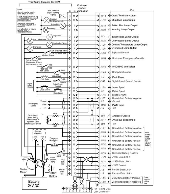
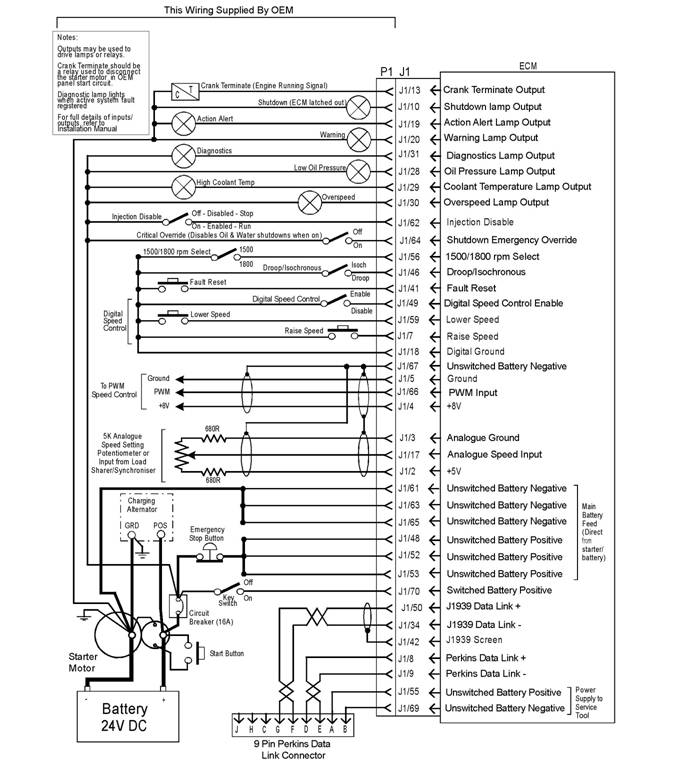
Illustration 8
Schematic diagram for a machine with an OEM connector
g01275859
![]()
![]()
![]() 20
20
Troubleshooting Section
KENR6224
Illustration 9
Schematic diagram for a machine without an OEM connector
g01275860
![]()
![]() KENR6224
KENR6224
21
Troubleshooting Section
Programming
Par ame ters
i02549443
Since factory passwords contain alphabetic
characters, the Perkins Electronic Service Tool
(EST) must be used to perform these functions. In
order to obtain factory passwords, proceed as if you
already have the pass word. If factory passwords are
Programming Parameters
The Perkins Electronic Service Tool (EST) can be
used to view certain parameters that can affect
the operation of the engine. The Perkins EST can
also be used to change certain parameters. The
parameters are stored in the Electronic Control
Module (ECM). Some of the parameters are
protected from unauthoriz ed changes by passwords.
Parameters that can be changed have a tattletale
number. The tattletale number shows if a parameter
has been changed.
i02549444
Factory Passwords
needed, the Perkins EST will request the factory
pas swords and the Perkins EST will display the
information that is required to obtain the passwords.
For the worksheet that is used for acquiring factory
passwords, refer to programming parameters
Troubleshooting, “Factory Passwords Worksheet”.
i02549455
Factory Passwords Worksheet
Note: A mistake in recording these parameters will
result in incorrect passwords.
NOTICE
Operating the engine with a flash file not des igned for
that engine will damage the engine. Be sure the flash
file is correct for your engine.
Note: Factory passwords are provided only to
Perkins dealers and distributors.
Factory passwords are required to perform each of
the following functions:
• Program a new Electronic Control Module (ECM).
When an ECM is replaced, the system
configuration parameters must be programmed
into the new ECM. A new ECM will allow these
parameters to be programmed once without factory
pas swords. After the initial programming, some
parameters are protected by factory passwords.
• Clear event codes.
Most event codes require the use of factory
pas swords to clear the code once the code has
been logged. Clear these codes only when you are
certain that the fault has been corrected.
• Unlock parameters.
Factory passwords are required in order to unlock
certain system configuration parameters. Refer
to Troubleshooting, “System Configuration
Parameters”.

![]() 22
22
Troubleshooting Section
KENR6224
Table 5
Factory Passwords Worksheet
Note: If you do not have the part number for the flash
file, us e “PTMI” on the Perkins Internet.
Dealer Code
Customer ’s Name
Address
Telephone Number
Information From the Engine Information Plate
Engine Serial Number
Full Load Setting
Full Torque Setting
Information From the Diagnostic Clock
Engine Hours
Information From the “Factory Password Entry
Screen” on the Electronic Service Tool
Electronic Service Tool
Serial Number
Engine Serial Number
ECM Serial Number
Total Tattletale
Reason Code
From Interlock(1)
To Interlock(1)
Fact ory Passwords
Factory Password (No. 1)
Factory Password (No. 2)
(1) This parameter is required when the engine is being rerated.
This parameter is displayed only when the engine is being
rerated.
i02549457
Flash Programming
Flash Programming – A method of loading a flash
file into the Electronic Control Module (ECM)
The electronic service tool can be utilized to
flash program a flash file into the ECM. The flash
programming transfers the flash file from the PC to
the ECM.
Flash Programming a Flash File
1. Obtain the part number for the new flash file.
Note: You must have the engine serial number in
order to search for the part number for the flash file.
2. Connect the electronic service tool to the service
tool connector.
3. Turn the keyswitch to the ON position. Do not start
the engine.
4. Select “WinFlash” from the “Utilities” menu on the
electronic service tool.
Note: If “WinFlash” will not communicate with the
ECM, refer to Troubleshooting, “Electronic Service
Tool Will Not Communicate with ECM”.
5. Flash program the flash file into the ECM.
a. Select the engine ECM under the “Detected
ECMs”.
b. Press the “Browse” button in order to select
the part number of the flash file that will be
programmed into the ECM.
c. When the correct flash file is selected, press
the “Open” button.
d. Verify that the “File Values” match the
application. If the “File Values” do not match
the application, search for the correct flash file.
e. When the correct flash file is selected, press
the “Begin Flash” button.
f. The electronic service tool will indicate when
flash programming has been successfully
completed.
6. Start the engine and check for proper operation.
a. If a diagnostic code 0268-02 is generated,
program any parameters that were not in the
old flash file.
b. Access the “Configuration” screen under
the “Service” menu in order to determine
the parameters that require programming.
Look under the “Tattletale” column. All of the
parameters should have a tattletale of 1 or
more. If a parameter has a tattletale of 0,
program that parameter.
![]() KENR6224
KENR6224
23
Troubleshooting Section
“WinFlash” Error Messages
If you receive any error messages during flash
programming, click on the “Cancel” button in order
to stop the process. Access the information about
the “ECM Summary” under the “Information” menu.
Ensure that you are programming the correct flash
file for your engine.
i02549465
Injector Trim File
The electronic service tool is used to load the injector
trim files into the Electronic Control Module (ECM).
The injector trim files must be loaded into the ECM if
5.
6.
7.
8.
9.
Connect the electronic service tool to the
service tool connector. Refer to Troubleshooting,
“Electronic Service Tools”.
Turn the keyswitch to the ON position.
Select the following menu options on the electronic
service tool:
• Service
• Calibrations
• Injector Trim Calibration
Select the appropriate cylinder.
Click on the “Change” button.
|
|
• An injector is replaced.
• The ECM is replaced.
• Diagnostic code 0253-02 is active.
• Injectors are exchanged between cylinders.
Exchanging Electronic Unit Injectors
Exchanging injectors can help determine if a fault is
in the injector or in the cylinder. If two injectors that
are currently installed in the engine are exchanged
between cylinders, the injector trim files can also
be exchanged. Press the “Exchange” button at the
bottom of the “Injector Trim Calibration” screen on
the electronic service tool. Select the two injectors
that will be exchanged and press the “OK” button.
The tattletale for the injectors that were exchanged
will increase by one.
Note: The serial number for the injector and the
confirmation code number for the injector are located
on the injector.
1. Record the serial number and the confirmation
code numberfor each injector.
2. Obtain the injector trim file by one of the following
methods:
Internet.
replacement injector.
3. Enter the serial number for the injector in the
search field.
4. Download the injec tor trim file to the PC. Repeat
this procedure for each injector, as required.
10. Select the appropriate injector trim file from the
PC.
11. Click on the “Open” button.
12. If you are prompted by the electronic service
tool, enter the confirmation code number for the
injector into the field.
13. Click on the “OK” button.
The injector trim file is loaded into the ECM.
14. Repeat the procedure for each cylinder, as
required.
![]() 24
24
Troubleshooting Section
KENR6224
System
Conf iguration
ECM Serial Number
This is a read only parameter that displays the serial
Parameters
System Configuration
Parameters
i02549472
number of the ECM.
ECM Software Release Date
This parameter is defined by the ECM software
and this parameter is not programmable. The ECM
software release date is used to provide the version
of the software. The customer parameters and the
software change levels can be monitored by this
System configuration parameters affect the emissions
of the engine or the power of the engine. System
configuration parameters are programmed at the
factory. Normally, system configuration parameters
would never need to be changed through the life of
the engine. System configuration parameters must
be reprogrammed if an Electronic Control Module
(ECM) is replaced. System configuration parameters
do not need to be reprogrammed if the ECM software
is changed. The correct values for these parameters
are stamped on the engine information ratings plate.
Factory passwords are required to change these
parameters. The following information is a description
of the system configuration parameters.
Full Load Setting (FLS)
The full load setting is a number that represents
the adjustment to the fuel system that was made
at the factory in order to fine tune the fuel sy stem.
The correct value for this parameter is stamped on
the engine information ratings plate. If the ECM is
replaced, the full load setting mus t be reprogrammed
in order to prevent a 0268-02 diagnostic code from
becoming active.
Full Torque Setting (FTS)
Full torque setting is similar to full load setting. If
the ECM is replaced, the full torque setting must
be reprogrammed in order to prevent a 0268-02
diagnostic code from becoming active.
Software Part number
This is the part number of the software that is flashed
into the ECM.
Engine Serial Number
When a new ECM is deliv ered, the engine serial
number in the ECM is not programmed. The engine
serial number should be programmed to matc h the
engine serial number that is stamped on the engine
information plate.
date. The date is provided in the month and the year
(AUG06). AUG is the month (August). 06 is the year
(2006).
Critical Override Switch
If equipped, the critical override switch allows the
engine to continue running even if engine oil pressure
or coolant temperature have reached the shutdown
limit for the engine. If the engine is run in this
condition, the engine warranty is canc elled and any
events that occur are s tored in the ECM with the time
and the date. Implementation of this facility requires
a fac tory password.
Total Tattletale
This parameter displays the total number of changes
that have been made to the configuration parameters.
![]() KENR6224
KENR6224
25
Troubleshooting Section
Configuration Parameters
Table 6
|
Screen Order |
Configuration Parameter Description |
Read/Write Security |
|
1 |
Selected Engine Rating |
|
|
2 |
Rating Number |
RW2(1) |
|
3 |
Rated Frequency |
R(2) |
|
4 |
Rated Genset Speed |
R(2) |
|
5 |
Rated Real Genset Power |
R(2) |
|
6 |
Rated Apparent Genset Power |
R(2) |
|
7 |
Engine Rating Application Type |
R(2) |
|
8 |
External Speed Selection Switch Installed |
RW2(1) |
|
9 |
ECM Identification Parameters |
|
|
10 |
Equipment ID |
RW2(1) |
|
11 |
Engine Serial Number |
RW3(3) |
|
12 |
ECM Serial Number |
R(2) |
|
13 |
ECM Software Part Number |
R(2) |
|
14 |
ECM Software Release Date |
R(2) |
|
15 |
ECM Software Description |
R(2) |
|
16 |
Security Access Parameters |
|
|
17 |
Total Tattl etale |
R(2) |
|
18 |
Engine/Gear Parameters |
|
|
19 |
Engine Acceleration Rate |
RW2(1) |
|
20 |
Droop/Isochronous Switch Installed. |
RW2(1) |
|
21 |
Droop/Isochronous Selection |
RW2(1) |
|
22 |
Engine Speed Droop |
RW2(1) |
|
23 |
Critical Override Switch Installed |
RW2(1) |
|
24 |
Digital Speed Control Installed |
RW2(1) |
|
25 |
Speed Control Minimum Speed |
RW2(1) |
|
26 |
Speed Control Maximum Speed |
RW2(1) |
|
27 |
Digital Speed Control Ramp Rate |
RW2(1) |
|
28 |
Crank Terminate Speed |
RW2(1) |
|
29 |
I/O Configuration Parameters |
|
|
30 |
Desired Speed Input Arrangement |
RW2(1) |
|
31 |
Fuel Enable Input Configurati on |
RW2(1) |
|
32 |
System Parameters |
|
|
33 |
Full Load Setting (FLS) |
RW3(3) |
|
34 |
Full Torque Setting (FTS) |
RW3(3) |
|
35 |
Governor Gain Factor |
RW1(4) |
|
36 |
Governor Minimum Stability Factor |
RW1(4) |
|
37 |
Governor Maximum Stability Factor |
RW1(4) |
(continued)
![]() 26
26
Troubleshooting Section
KENR6224
(Table 6, contd)
|
38 |
Passwords |
|
|
39 |
Customer Password 1 |
RW2(1) |
|
40 |
Customer Password 2 |
RW2(1) |
(1)
(2)
(3)
(4)
Read/write with a customer password
Read only
Read/write with a factory password
Read/write without a password
Customer Specified Parameters
Customer specified parameters allow the engine to
be configured to the exact needs of the application.
Customer parameters may be changed repeatedly as
a customer’s operation changes.
The following information is a brief desc ription of the
customer specified parameters.
Rating Duty Selection
This parameter enables selection of the engine rating
from a series of maps within the ECM. Changing the
rating requires a cus tomer password. The available
ratings within the ECM will vary with the type of
engine and the specification of the engine.
Rated Frequency
This parameter displays the rated frequency of the
genset. This is determined by the rating selection
and the status of the external speed selection s witch.
This parameter is read only.
Rated Speed
This parameter displays the rated speed of the
engine. This is determined by the rating selection
and the status of the external speed selection s witch.
This parameter is read only.
Rated Real Genset Power
This parameter displays the maximum power in kW
of the currently s elected rating. This parameter is
read only.
Rated Apparent Genset Power
This parameter displays the maximum power in kVA
of the currently s elected rating. This parameter is
read only.
Rating Configuration
This parameter displays the configuration of the
currently selected rating. The following list gives the
possible configurations:
• Standby power
• Limited time prime power
• Prime power
• Continuous or baseload power
For definitions of these ratings, refer to ISO8528.
This parameter is read only.
Note: Not all of the above rating configurations will
be available in the software files of every ECM.
E xternal Speed Selection Switch Enable
For dual s peed applications with an external
speed selection switch, this parameter enables the
functionality of the speed selection switch within
the s oftware. Changing this parameter requires a
customer password.
Engine Startup Acceleration Rate
This parameter enables the ac celeration rate of
the engine in RPM per second to be programmed.
The parameter can be programmed from idle speed
to rated speed. Control of this parameter enables
any overshoot in speed on start-up to be limited.
Changing this parameter requires a c ustomer
pas sword.
Droop/Isochronous Switch Enable
This parameter determines whether the external
droop/isochronous switch is enabled or disabled.
Changing this parameter requires a c ustomer
pas sword.
![]() KENR6224
KENR6224
27
Troubleshooting Section
Droop/Isochronous Selection
The engine will normally be run in isochronous mode.
This means that the engine speed will not change,
regardless of the load. If the engine needs to operate
in parallel with another genset or the engine needs
to operate in parallel with the grid, it is nec essary to
operate the engine in droop mode in order to ensure
the stability of the system. This parameter enables
droop/isochronous running selection. Changing this
parameter requires a customer pass word.
Note: If an external droop/isochronous switch is
enabled, the position of this switch will override the
“Droop/Is ochronous” selection.
Engine Speed Droop
If droop operation is selected, this parameter
allows the setting of percentage droop. This is the
percentage of speed reduction with an increase in
load. This parameter has no effect when the engine
is running in isochronous mode. Changing this
parameter requires a customer pass word.
Digital Speed Cont rol Installed
This parameter determines whether input from the
raise/lower switch controls the speed of the engine.
If digital speed control is not installed, the speed of
the engine is controlled by inputs from the analog
throttle or the PWM throttle. This depends on the
input that is selected in the desired speed input
configuration. Changing this parameter requires a
customer password.
Digital S peed Control Minimum Speed
This setting determines the minimum speed range of
both the raise/lower control and the analog control.
For example, if this is set to 100 RPM and the
nominal engine speed is s elected to 1500 RPM, the
minimum speed setting is 1400 RPM. This parameter
does not affect the range of the PWM speed control
as this control has a fixed minimum limit and a fixed
maximum limit. Changing this parameter requires a
customer password.
Digital S peed Control Maximum Speed
This setting determines the maximum speed range of
both the raise/lower control and the analog control. If
this is set to 100 RPM and the nominal engine speed
is selected to 1500 RPM, the maximum speed setting
is 1600 RPM. This setting does not affect the range
of the PWM speed control as this c ontrol has a fixed
minimum limit and a fixed maximum limit. Changing
this parameter requires a customer password.
Digital Speed Control Ramp Rate
This setting determines the rate of change of engine
speed in RPM when the raise/lower switch inputs are
closed. Changing this parameter requires a customer
pas sword.
Crank Terminate Speed
This parameter is used to set the engine speed that
is required before the output from the crank terminate
relay is switched. Changing this parameter requires a
customer password.
Desired Speed Input Arrangement
If a digital speed control is not installed, this
parameter enables selection of either an analog
throttle, a PWM throttle or an ex ternal CAN Bus
speed control. The inputs from the analog throttle,
the PWM throttle or the CAN Bus speed control
are normally used with genset load sharing and
synchronizing controllers. Changing this parameter
requires a customer password.
Note: If a PWM throttle, an analog throttle or a CAN
Bus speed control is selected but there are no inputs
to the terminals for the selected speed control, the
engine will default to running at 1100 RPM.
If a PWM throttle, an analog throttle or a CAN Bus
speed control is not used, the digital s peed control
should be selected.
Fuel Enable Input Configuration
This parameter enables the selection of switch to
battery positive or CAN input for the control of the
injector On and injector Off.
Governor Gain Parameters
The following items are the adjustable parameters for
gov ernor gain:
• Governor Gain Factor
• Governor Minimum Stability Factor
• Governor Maximum Stability
Note: No engineering units are associated with these
numbers.
Note: The programmable range is wide for flexibility.
Values of 1 to 40000 are valid. The full range of this
parameter may not be used on any system. Do not
expect to use the whole range.
![]()
![]() 28
28
Troubleshooting Section
KENR6224
|
|
Governor Gain Factor
The governor gain factor is multiplied to the difference
between desired speed and actual speed.
large, the engine speed can overshoot the desired
speed. The overshoot is caused by an excessive
correction or an instability of a steady state.
that is nec essary to accelerate the engine to the
des ired speed must be obtained by increas ing the
stability terms to a higher value. As this process is
slow, the response of the engine speed is slow.
Governor Minimum/Maximum Stability
Factor
The stability factor terms work in order to eliminate a
steady state speed error. There are two gain terms
that are used for stability. If the error is greater than
20 RPM and if the error is increasing, the maximum
stability gain is functioning. If the error is less than
20 RPM, the minimum stability gain is used. This
function allows the use of a high gain that would
2.
3.
4.
5.
6.
Start the engine. On the engine mounted genset
control panel, check that the engine has reached
rated speed. This panel will serve as the reference
point for the speed during this procedure.
Enter the “Configuration Parameters” screen on
the electronic service tool.
Determine the desired scenario in order to tune
the engine. For example, check if the engine has
poor response during specific load assignments
or specific load dumps.
Perform the desired load change that is detailed
in step 4. Check the response of the engine by
viewing the following parameters.
• The engine speed on the control panel on the
genset
• The frequency response of the system bus to
the load change
• Listening to the response of the engine
Use the listed suggestions in order to determine
the gains that require adjustment.
|
|
engine is operating near the desired speed.
stability gain is set too high, the governor will
provide more fuel than the amount that is
nec essary to bring the error to zero. The additional
fuel will cause the engine speed to overshoot and
the engine to produce excessive combustion noise.
stability gain is set too low, excessive time is taken
in order to stabilize the engine s peed.
Tuning Procedure
1. Turn the keyswitch to the OFF/RESET position.
Before the tuning procedure is started, connect
the electronic serv ice tool and then check
that engine overspeed protection is enabled.
Engine overspeed is configured on the
“Service\Monitoring System” sc reen on the
electronic service tool.,
NOTICE
Performing engine governor tuning without engine
overspeed protection could result in serious engine
damage. Ens ure that this parameter is ON while
performing this proc edure.
Note: Usually, the gain factor of the governor should
be lower than the minimum stability fac tor of the
gov ernor in order to obtain optimum performance.
The maximum stability factor is typically a smaller
value than the minimum stability gain and the
gov ernor gain factor.
7. Repeat steps 5, 6 and 7 until a desired engine
response can be met. Use large adjustments
(10% of original gain) initially to generally tune the
engine in the proper manner. As the response
gets closer to the desired value, increase the
gains in smaller increments (1% of total gain).
Customer Password 1, Customer
Password 2
Customer passwords are the programmable
parameters that can be used to protect certain
configuration parameters from any unauthorized
changes.
Engine monitoring
Perkins provides an engine monitoring system that
is ins talled at the factory. The system monitors the
following parameters:
• Engine oil pressure
• Coolant temperature
![]() KENR6224
KENR6224
29
Troubleshooting Section
•
•
•
•
Intake manifold air temperature
Engine speed
Boost pressure
Fuel temperature
Diagnostic codes that are stored in memory are
called Logged diagnostic codes. The fault may have
been temporary or the fault may hav e been repaired
since the fault was logged. For this reason, logged
codes do not necessarily mean that something needs
to be repaired. Logged diagnostic codes are meant
to be an indication of probable causes for intermittent
faults.
The monitoring system has three levels of operation.
The levels are described below.
Warning Operation
In the Warning condition, the ECM causes the
warning lamp to come ON. The warning lamp
indicates that a fault has been detected by the engine
monitoring system. No further action by the ECM or
the engine occurs.
Action Alert Operation
In the Action Alert condition, the ECM causes the
action alert lamp to come on. The Action Alert lamp
indicates that a fault has been detected by the engine
monitoring system. This condition is normally wired
in order to cause a shutdown and the shutdown is
controlled by the control panel on the mac hine.
Shutdown Operation
If the fault reaches the Shutdown c ondition, the ECM
causes the shutdown lamp to come on. Unless the
engine is in a Critical Override condition, the engine
will shut down.
Monitoring the Fuel Temperature
The fuel temperature sensor monitors the fuel
temperature. The signal from the sensor allows
the ECM to compensate for changes in the fuel
temperature by adjusting the fuel rate for constant
power.
The sensor is also used to warn the operator of
exces sive fuel temperature with a diagnostic event
code. Excessive fuel temperatures can adversely
affect engine performance.
Self-Diagnostics
The electronic system has the ability to diagnose
faults. When a fault is detected, a diagnostic code
is generated and the diagnostic code is stored
in permanent memory (logged) in the ECM. The
diagnostic lamp is also activated.
When diagnostic codes occur, the diagnostic codes
are referred to as Active diagnostic codes. Active
diagnostic c odes indicate that a fault of some kind
currently exists.
Diagnostic codes that identify operating conditions
outside the normal operating range are called Events.
Event codes are not typically an indication of a fault
with the electronic system.
Note: Some of the diagnostic codes require
pas swords to clear the code.
Effect of Diagnostic Codes on
Engine Performance
The diagnostic lamp comes on when a specific
condition exists. When the ECM detects an engine
fault, the ECM generates an active diagnostic code
and the diagnostic code is logged. The diagnostic
code is logged in order to record the following
information:
• The date
• The time
• The number of occurrences of the fault
The two types of diagnostic codes are Fault codes
and Event codes.
Fault Codes
Fault codes are provided in order to indicate that
an electrical fault or an electronic fault has been
detected by the ECM. In some cases, the engine
performance can be affected by the condition that is
causing the code. More frequently, there is no effect
on engine performance.
Event Codes
Event codes are used to indicate that some
operational fault has been detected in the engine by
the ECM. This does not usually indicate an electronic
malfunction.
The ECM also provides a cloc k in order to add the
date and the time to the following critical event codes:
• 360-3 Low oil pressure shutdown
• 361-3 High coolant temperature shutdown

![]() 30
30
Troubleshooting Section
KENR6224
Refer to the Troubleshooting Guide, “Diagnostic
Code Cross Reference” for a list of all the diagnostic
fault codes.
Settings for the Monitoring System
Table 7
Parameter
Low Engine Oil Pressure
Warn Operator (1)
On
State
Trip Point
300 kPa (43.5 psi)
Delay Time
60 seconds
Action Alert (2)
Engine Shutdown (3)
High Engine Coolant Temperature
Warn Operator (1)
Action Alert (2)
Engine Shutdown (3)
Engine Overspeed
Warn Operator (1)
Action Alert (2)
Engine Shutdown (3)
High Intake Manifold Air Temperature
Warn Operator (1)
Action Alert (2)
High Fuel Supply Temperature
Warn Operator (1)
Action Alert (2)
High Boost Pressure
Warn Operator (1)
Action Alert (2)
Always On
Always On
On
Always On
Always On
On
Always On
Always On
On
Always On
On
Always On
On
Always On
None
None
104 °C (2190 °F)
105 °C (221 °F)
108 °C (226 °F)
2000 RPM
2050 RPM
2140 RPM
75 °C (167 °F)
78 °C (172 °F)
60 °C (140 °F)
68 °C (154 °F)
300 kPa (43.5 psi)
None
2 seconds
2 seconds
60 seconds
10 seconds
10 seconds
1 second
1 second
0 second
60 seconds
10 seconds
60 seconds
60 seconds
30 seconds
5 seconds
![]() KENR6224
KENR6224
31
Troubleshooting Section
Troubleshoot ing
Diagnosti c Code
without
a
Alternator Will Not Charge
i02556542
Alternator Noise
Note: This is not an electronic system fault.
i02556541
Note: This is not an electronic system fault.
Probable Causes
• Alternator drive belt
• Charging circuit
Refer to Testing and Adjusting for information on
possible electrical causes of this condition.
Probable Causes
•
Alternator
•
•
•
•
Alternator drive belt
Alternator mounting bracket
Alternator drive pulley
Alternator bearings
Recommended Actions
Alternator Drive Belt
Inspect the condition of the alternator drive belt. If
the alternator drive belt is worn or damaged, chec k
that the drive belt for the alternator and the pulley are
correctly aligned. If the alignment is correct, replace
the drive belt. Refer to Systems Operation, Testing
and Adjusting, “Belt Tension Chart”.
Recommended Actions
Alternator Drive Belt
Inspect the condition of the alternator drive belt. If
the alternator drive belt is worn or damaged, check
that the drive belt for the alternator and the pulley are
correctly aligned. If the alignment is correct, replace
the drive belt. Refer to Disassembly and Assembly,
“Alternator Belt - Remove and Install”.
Alternator Mounting Bracket
Inspect the alternator mounting bracket for cracks
and wear. Repair the mounting bracket or replace
the mounting bracket in order to ensure that the
alternator drive belt and the alternator drive pulley
are in alignment.
Alternator Drive Pulley
Remove the nut for the alternator drive pulley and
then inspect the nut and the drive shaft. If no damage
is found, install the nut and tighten the nut to the
correct torque. Refer to Specifications, “Alternator
and Regulator” for the correct torque.
Alternator Bearings
Check for excessive play of the shaft in the alternator.
Check for wear in the alternator bearings. The
alternator is a nonserviceable item. The alternator
must be replaced if the bearings are worn. Refer to
Disassembly and Assembly, “Alternator - Remove”
and Disassembly and Assembly , “Alternator - Install”.
Charging Circuit
Inspect the battery cables, wiring, and connections in
the charging circuit. Clean all connections and tighten
all connections. Replac e any faulty parts.
Alternator
Verify that the alternator is operating correctly.
Refer to Systems Operation, Testing and Adjusting,
“Charging System - Test”. The alternator is not a
serviceable item. The alternator must be replaced
if the alternator is not operating correctly. Refer to
Disassembly and Assembly, “Alternator - Remove
and Install”.
i02556551
Battery
Note: This is not an electronic system fault.
Probable Causes
• Charging circuit
• Battery
• Auxiliary dev ice
![]()
![]()
![]() 32
32
Troubleshooting Section
KENR6224
Recommended Actions
Charging Circuit
If a fault in the battery charging c ircuit is suspected,
refer to Troubleshooting, “Alternator Will Not Charge”.
Battery
1. Check that the battery is able to maintain a charge.
•
•
•
•
•
Rated fuel position and/or FRC fuel position
Inlet manifold pressure sensor
Fuel supply
Air inlet and exhaust system
Accessory equipment
2.
Refer to Testing and Adjusting, “Battery - Test”.
If the battery does not maintain a charge,
replace the battery. Refer to the Operation and
Maintenance Manual, “Battery - Replace”.
Recommended Actions
Diagnostic Codes and Event Codes
Certain diagnostic codes and/or event codes may
cause poor performance. Connect the electronic
service tool and then check for active codes and
Auxiliary Device
1. Check that an auxiliary device has drained the
battery by being left in the ON position.
2. Charge the battery.
3. Verify that the battery is able to maintain a charge
when all auxiliary devices are switched off.
i02556559
Can Not Reach Top Engine
RPM
Note: If this fault occurs only under load, refer to
the Troubleshooting Guide, “Low Power/Poor or No
Response to Throttle”.
The connection of any electrical equipment and
the disconnection of any electrical equipment may
cause an explosion hazard which may result in in-
jury or death. Do not connect any electrical equip-
ment or disconnect any electrical equipment in an
explosive atmosphere.
Probable Causes
• Diagnostic codes
• Event codes
• Programmable parameters
• Cold mode
• Throttle signal
logged codes. Troubleshoot any codes that are
present before continuing with this procedure.
Programmable Parameters
Check the following parameters on the electronic
service tool:
• “Des ired Engine Speed”
• “Desired Speed Input Configuration”
Determine the type of speed control that is used in
the applic ation. Program the parameters to match
the type of speed control that is used. Refer to the
Troubleshooting Guide, “Speed Control Circuit - Test”
for more information.
Note: The engine will have poor performance if the
parameters are not programmed correctly.
Cold Mode
Use the electronic service tool to verify that the
engine has exited cold mode. A status flag will
appear if the engine is operating in cold mode. This
may limit engine speed.
Throttle Signal
Connect the electronic service tool to the diagnostic
connector. View the status for the “Desired Engine
Speed” on the status screen. Operate the speed
control from the Low Speed position to the High
Speed position. If the status cannot operate in the full
range, refer to the Troubleshooting Guide, “Speed
control - Calibrate”.
![]() KENR6224
KENR6224
33
Troubleshooting Section
Diagnostic codes that are related to the J1939 data
link will prevent correct operation of the throttle if the
throttle position is transmitted over the data link. If
there is a fault in the data link, the engine will remain
at low idle until the data link is repaired.
Inlet Manifold Pressure Sensor, Rated
Fuel Position and/or FRC Fuel Position
1. With the engine at full load, monitor “Fuel Position”
and “Rated Fuel Limit” on the status screen. If
“Fuel Position” does not equal “Rated Fuel Limit”
then check air inlet manifold pressure.
2. Verify that there are no active diagnostic codes
that are associated with the inlet manifold pressure
sensor or with the atmospheric pressure sensor.
3. Monitor the inlet manifold pressure and the
atmospheric pressure on the status screen for
normal operation.
Fuel Supply
1. Check the fuel lines for the following faults:
restrictions, collapsed lines, and pinched lines. If
faults are found with the fuel lines, repair the lines
and/or replace the lines.
2. Check the fuel tank for foreign objects which may
block the fuel supply.
3. Prime the fuel system if any of the following
procedures have been performed:
• Replacement of the fuel filters
• Service on the low pressure fuel supply circuit
• Replacement of electronic unit injectors
Note: A sight glass in the low pressure supply line is
helpful in diagnosing air in the fuel. Refer to Systems
Operation, Testing and Adjusting.
4. Cold weather adversely affects the characteristics
of the fuel. Refer to the Operation and
Maintenance Manual for information on improving
the c haracteristics of the fuel during cold weather
operation.
5. Check the fuel pressure during engine cranking.
Check the fuel pressure on the outlet side of
the fuel filter. Refer to Specifications for correct
pressure values. If the fuel pressure is low,
replace the fuel filters. If the fuel pressure is still
low, check the following items: fuel transfer pump,
fuel transfer pump coupling, and fuel pressure
regulating valve.
Air Inlet and Exhaust System
1. Clean plugged air filters or replace plugged air
filters. Refer to the Operation and Maintenance
Manual.
2. Check the air inlet and exhaust system for
restrictions and/or leaks. Refer to Systems
Operation, Testing and Adjusting, “Air Inlet and
Exhaust System”.
Accessory Equipment
Check all accessory equipment for faults that may
create excessive load on the engine. Repair any
damaged components or replace any damaged
components.
i02556728
Coolant in Engine Oil
Probable Causes
• Engine oil cooler core
• Cylinder head gasket
• Cylinder head
• Cylinder liner
• Cylinder block
Recommended Actions
Engine Oil Cooler Core
1. Check for leaks in the oil cooler core. If a leak is
found, install a new oil cooler core. Refer to the
Disassembly and Assembly manual.
2. Drain the crankcase and refill the crankcase with
clean engine oil. Install new engine oil filters.
Refer to the Operation and Maintenance Manual.
Cylinder Head Gasket
1. Remove the cylinder head. Refer to the
Disassembly and Assembly manual.
2. Check the cylinder liner projection. Refer to the
Systems Operation, Testing and Adjusting manual.
3. Install a new cylinder head gasket and new water
seals in the spacer plate. Refer to the Disassembly
and Assembly manual.
![]() 34
34
Troubleshooting Section
KENR6224
Cylinder Head
Check for cracks in the cylinder head. If a crack
is found, repair the cylinder head and/or replace
the cylinder head. Refer to the Disassembly and
Assembly manual.
Cylinder Liner
Check for cracked cylinder liners. Replace any
cracked cylinder liners. Refer to the Disassembly and
Assembly manual.
Cylinder Block
Inspect the cylinder block for cracks. If a crack is
found, repair the cylinder block or replace the cylinder
block.
2.
3.
Verify that the electronic service tool is on the
“Factory Password” screen.
Use the electronic service tool to verify that the
following information has been entered correctly:
• Engine serial number
• Serial number for the electronic control module
• Serial number for the electronic service tool
• Total tattletale
• Reason code
i02556747
ECM Will
Not
Communicate
Coolant Temperature
High
Is
i02556737
Too
with Other Systems
Modules
Probable Causes
or Display
Refer to Systems Operation, Testing and Adjusting,
“Cooling System - Check” for information on
determining the cause of this condition.
i02556740
ECM Will Not Accept Factory
Passwords
•
•
•
•
Wiring and/or electrical connectors
Data Link
CAN data link (if equipped)
Electronic Control Module (ECM)
Probable Causes
One of the following items may not be recorded
correctly on the electronic service tool:
• Passwords
• Serial numbers
• Total tattletale
• Reason code
Recommended Actions
1. Verify that the correct passwords were entered.
Check every c haracter in each password. Remove
the electrical power from the engine for 30
seconds and then retry.
Recommended Actions
1. Check for correct installation of the J1/P1 and
J2/P2 connectors for the Electronic Control
Module (ECM) . Refer to the Troubleshooting
Guide, “Electrical Connectors - Inspect”.
2. Connect the electronic service tool to the
diagnostic connec tor. If the ECM does not
communicate with the electronic service tool, refer
to the Troubleshooting Guide, “Electronic Service
Tool Will Not Communicate with ECM”.
3. Troubleshoot the data link for possible faults.
Refer to the Troubleshooting Guide, “Data Link
Circ uit - Test”.
4. Troubleshoot the CAN data link (if equipped)
for poss ible faults. Refer to the Troubleshooting
Guide, “CAN Data Link Circuit - Test”.
![]() KENR6224
KENR6224
35
Troubleshooting Section
Electronic
Service
Tool
i02557746
Will
Communication Adapter and/or Cables
1. If you are using a “Communication Adapter II”,
ensure that the firmware and driver files for the
Not Communicate with ECM
Probable Causes
• Configuration for the communic ations adapter
• Electrical connectors
• Communication adapter and/or cables
• Electrical power supply to the diagnostic connector
• Electronic service tool and related hardware
2.
3.
communication adapter are the most current files
that are available. If the firmware and driver files
do not match, the communication adapter will not
communicate with the electronic service tool.
Disconnect the communication adapter and the
cables from the diagnostic connector. Reconnect
the communication adapter to the service tool
connector.
Verify that the correct cable is being used between
the communication adapter and the diagnostic
connector. Refer to the Troubleshooting Guide,
“Electronic Service Tools”.
•
•
•
Electrical power supply to the Electronic Control
Module (ECM)
Flash file
Data Link
Electrical Power Supply to the Service
Tool Connector
Verify that battery voltage is present between
terminals A and B of the diagnostic connector. If the
communication adapter is not receiving power, the
display on the communication adapter will be blank.
Recommended Actions
Start the engine. If the engine starts, but the ECM
will not communicate with the electronic service tool,
continue with this procedure. If the engine will not
start, refer to the Troubleshooting Manual, “Engine
Cranks but Will Not Start”. If the engine will not crank,
refer to the Troubleshooting Guide, “Engine Will Not
Crank”.
Configuration for the Communications
Adapter
1. Access “Preferences” under the “Utilities” menu
on the electronic serv ice tool.
2. Verify that the correct “Communications Interface
Device” is selected.
3. Verify that the correct port is selected for use by
the communication adapter.
Note: The most commonly used port is “COM 1”.
4. Check for any hardware that is utilizing the
same port as the c ommunications adapter. If any
devices are configured to use the same port, exit
or close the software programs for that device.
Electrical Connectors
Check for correct installation of the J1/P1 and J2/P2
ECM connectors and of the diagnostic connector.
Refer to the Troubleshooting Guide, “Electrical
Connectors - Inspect”.
Electronic Service Tool and Related
Hardware
In order to eliminate the electronic service tool
and the related hardware as the fault, connect the
electronic service tool to a different engine. If the
same fault occ urs on a different engine, check the
electronic service tool and the related hardware in
order to determine the cause of the fault.
Electrical Power S upply to the Electronic
Control Module ( ECM)
Check power to the ECM. Refer to the
Troubleshooting Guide, “Electrical Power Supply
Circuit - Test”.
Note: If the ECM is not receiving battery voltage, the
ECM will not communicate.
Flash File
Ensure that the correct flash file is properly ins talled
in the ECM.
Note: A new ECM is not programmed to any specific
engine until a flash file has been installed. The engine
will not start and the engine will not communicate
with the electronic service tool until the flash file
has been downloaded. Refer to the Troubleshooting
Guide, “Flash Programming”.
![]() 36
36
Troubleshooting Section
KENR6224
Data Link
•
Replacement of electronic unit injectors
|
theTroubleshooting Guide, “Data Link Circuit - Test”.
i02557749
Engine Cranks but Will Not
Start
Probable Causes
• Fuel supply
• Diagnostic codes and event codes
(ECM)
• Flash file
• Remote s hutdown switch
• Starting motor, solenoid, or starting circuit
• Position sensors
• Electronic unit injector
• Combustion
Recommended Actions
Fuel Supply
1. Visually check the fuel level. Do not rely on the fuel
gauge only. If necessary, add fuel. If the engine
has been run out of fuel, it will be nec essary to
purge the air from the fuel system. Refer to the
Operation and Maintenance Manual, “Fuel System
- Prime” for the correct procedure.
2. Check the fuel lines for the following faults:
restrictions, collapsed lines, and pinched lines. If
faults are found with the fuel lines, repair the lines
and/or replace the lines.
3. Check the fuel tank for foreign objects which may
block the fuel supply.
4. Prime the fuel system if any of the following
procedures have been performed:
• Replacement of the fuel filters
• Servic e on the low pressure fuel supply circuit
Note: A sight glass in the low pres sure supply line
is helpful in diagnosing air in the fuel. Refer to
Systems Operation, Testing and Adjusting for more
information.
5. Check the fuel filters.
6. Cold weather adversely affects the characteristics
of the fuel. Refer to the Operation and
Maintenance Manual for information on improving
the characteristics of the fuel during cold weather
operation.
7. Check the fuel pressure during engine cranking.
Check the fuel pressure after the fuel filter. Refer
to Systems Operation/Testing and Adjusting, “Fuel
System” for the correct pressure values. If the fuel
pressure is low, replace the fuel filters. If the fuel
pressure is still low, check the following items: fuel
transfer pump, fuel transfer pump coupling, and
fuel pressure regulating valv e.
Diagnostic Codes and Event Codes
Certain diagnostic codes and/or event codes may
prevent the engine from starting. Connect the
electronic service tool and check for active codes
and/or for logged codes. Troubleshoot any codes that
are present before continuing with this procedure.
Electrical Power Supply to the ECM
If the ECM is not rec eiving battery voltage, the ECM
will not operate. Refer to the Troubleshooting Guide,
“Electrical Power Supply Circuit - Test”.
Starting Motor, Solenoid, or Starting
Circuit
Remove the starting motor and v isually inspect the
pinion of the starting motor and the flywheel ring gear
for damage.
Test the operation of the starting motor solenoid.
Check the condition of the engine wiring for the
starting motor solenoid. Test the operation of the
starting motor.
If necessary, repair the starting motor or the starting
circuit.
![]() KENR6224
KENR6224
37
Troubleshooting Section
Position Sensors
1. Crank the engine and observe the engine speed
on the status screen of the electronic service
tool. If the electronic service tool indicates zero
rpm, refer to the Troubleshooting Guide, “Engine
Position Sensor Circuit - Test”.
Note: Upon initial cranking, the status for engine
speed may indicate that the engine speed signal is
abnormal. This message will be replaced with an
engine s peed once the ECM is able to calculate a
speed from the signal.
2. If an engine s peed is present, check the sensor
ins tallation. If the sensor is not properly installed,
the ECM may read engine speed, but the ECM
cannot determine the tooth pattern. The ability for
the ECM to read the tooth pattern is necessary
to determine the cylinder position. Engine speed
is present when engine speed is greater than 50
rpm. Refer to the Troubleshooting Guide, “Engine
Position Sensor Circuit - Test”.
Electronic Unit Injector
1. Ensure that the valve cover connectors for the
injector harnesses are fully connected and free of
corrosion.
2. Perform the “Injector Solenoid Test” on the
electronic service tool in order to determine if all
of the injector solenoids are being energized by
the ECM. Refer to the Troubleshooting Guide,
“Injector Solenoid Circuit - Test” for additional
information.
Combustion
Check the engine for faults in the combustion system.
i02557751
Engine Has Early Wear
Probable Causes
• Incorrect engine oil
• Contaminated engine oil
• Contaminated air
• Contaminated fuel
• Low oil pressure
Recommended Actions
Incorrect Engine Oil
Use engine oil that is recommended and change the
engine oil at the interval that is recommended by the
Operation and Maintenance Manual.
Contaminat ed Engine Oil
Drain the crankcase and refill the crankcase with
clean engine oil. Ins tall new engine oil filters. Refer to
the Operation and Maintenance Manual.
If the oil filter bypass valve is open, the oil will not
be filtered. Check the oil filter bypass valv e for a
weak spring or for a broken spring. If the spring is
broken, replace the spring. Refer to the Disassembly
and Assembly manual. Make sure that the oil bypass
valve is operating correctly.
Contaminated Air
Inspect the air inlet system for leaks. Inspect all of
the gaskets and the connections. Repair any leaks.
Inspect the air filter. Replace the air filter, if necessary.
Contaminated Fuel
Inspect the fuel filter. Replace the fuel filter, if
nec essary.
Contaminants in the fuel such as hy drogen sulfide
and sulfur can lead to the formation of acids in the
crankcase. Obtain a fuel analysis.
Low Oil Pressure
When some components of the engine show bearing
wear in a short time, the cause can be a restriction in
a passage for engine oil.
An indicator for the engine oil pressure may indicate
sufficient pressure, but a component is worn due to a
lack of lubrication. In s uch a case, look at the passage
for the engine oil supply to the component. Refer
to the Systems Operation, Testing and Adjusting
manual.
![]() 38
38
Troubleshooting Section
KENR6224
Engine
i02557754
Misfires, Runs Rough
Electrical Connectors
Check the connectors for the Electronic Control
Module (ECM) and the connectors for the unit
or Is
Unstable
injectors for correc t installation. Refer to the
Troubleshooting Guide, “Electrical Connec tors -
Inspect”.
Note: If the symptom is intermittent and the symptom
cannot be repeated, refer to Troubleshooting,
“Intermittent Low Power or Power Cutout”. If the
symptom is consistent and the symptom can be
repeated, continue with this procedure.
Probable Causes
• Diagnostic codes
• Programmable parameters
• Electrical connectors
• Cold mode
• Speed control
• Electronic unit injectors
• Fuel supply
• Air inlet and exhaust system
Recommended Actions
Note: If the symptom only oc curs under certain
operating conditions (full load, engine operating
temperature, etc), test the engine under those
conditions. Troubleshooting the symptom under other
conditions can give misleading results.
Diagnostic Codes
Check for active diagnos tic c odes on the electronic
service tool. Troubleshoot any active codes before
continuing with this procedure.
Programmable Parameters
Check the “Desired speed input configuration” on the
electronic service tool.
Note: The engine will have poor performance if the
parameter is not programmed c orrectly.
Cold Mode
Use the electronic service tool to verify that the
engine has exited cold mode. Cold mode operation
may cause the engine to run rough and the engine
power may be limited.
Speed Control
Monitor the signal from the speed control on the
electronic service tool. Verify that the signal from the
speed control is stable from the low speed position to
the high s peed position.
Electronic Unit Injectors
1. Use the electronic service tool to determine if
there are any active diagnostic codes for the
electronic unit injectors.
2. Perform the injector solenoid test on the electronic
service tool in order to determine if all of the
injector solenoids are being energized by the
ECM. Refer to the Troubleshooting Guide,
“Injector Solenoid Circuit - Test” for the proper
procedure.
3. Perform the cylinder cutout test on the electronic
service tool in order to identify any electronic
unit injectors that might be mis firing. Refer to the
Troubleshooting Guide , “Injector Solenoid Circuit
- Test” for the proper procedure.
Fuel Supply
1. Check the fuel lines for the following faults:
restrictions, collapsed lines , and pinched lines. If
faults are found with the fuel lines, repair the lines
and/or replace the lines.
2. Check the fuel tank for foreign objects which may
block the fuel supply.
3. Prime the fuel system if any of the following
procedures have been performed:
• Replacement of the fuel filters
• Service on the low pressure fuel supply circuit
• Replacement of unit injectors
![]() KENR6224
KENR6224
39
Troubleshooting Section
Note: A sight glass in the low pressure supply line is
helpful in diagnosing air in the fuel.
4. Cold weather adversely affects the characteristics
of the fuel. Refer to the Operation and
Maintenance Manual for information on improving
the c haracteristics of the fuel during cold weather
operation.
5. Check the fuel pressure during engine cranking.
Check the fuel pressure after the fuel filter. Refer
to Systems Operation, Testing and Adjusting,
“Fuel System” for the correct pressure values. If
the fuel pressure is low, replace the fuel filters. If
the fuel pressure is still low, check the following
items: fuel transfer pump, fuel transfer pump
coupling, and fuel press ure regulating valve.
Air Inlet and Exhaust System
1. Check for an air filter restriction. Clean plugged air
filters or replace plugged air filters. Refer to the
Operation and Maintenance Manual for additional
information.
2. Check the air inlet and exhaust system for
restrictions and/or for leaks. Refer to Systems
Operation, Testing and Adjusting, “Air Inlet and
Exhaust System”.
i02557763
Engine Oil in Cooling System
Probable Causes
• Engine oil cooler core
• Cylinder head gasket
Recommended Actions
Engine Oil Cooler Core
1. Inspect the engine oil cooler c ore for leaks. If a
leak is found, replace the oil cooler core. Refer to
Disassembly and Assembly, “Engine Oil Cooler
- Remove” and Disassembly and Assembly,
“Engine Oil Cooler - Install”.
2. Drain the crankcase and refill the crankcase with
clean engine oil. Ins tall new engine oil filters.
Refer to the Operation and Maintenance Manual
for more information.
Cylinder Head Gasket
1. Remove the cylinder head. Refer to Disassembly
and Assembly, “Cylinder Head - Remove” for the
correct procedure.
2. Check the cylinder liner projection. Refer to
Systems Operation, Testing and Adjusting for the
correct procedure.
3. Install a new cylinder head gasket and new water
seals in the spacer plate. Refer to Disassembly
and Assembly, “Cylinder Head - Install” for the
correct procedure.
i02557773
Engine Vibration
Probable Causes
• Vibration damper
• Engine supports
• Driven equipment
• Engine misfiring or running rough
Recommended Actions
Vibration Damper
Check the vibration damper for damage. Install a
new vibration damper, if necessary. Inspect the
mounting bolts for damage and/or for wear. Replace
any damaged bolts. Refer to the Disassembly and
Assembly manual.
Engine Supports
Inspect the mounts and the brackets while you run
the engine through the speed range. Look for mounts
and brackets that are loose and/or broken. Tighten
all of the mounting bolts. Install new components, if
nec essary.
Driven Equipment
Check the alignment and the balance of the driven
equipment.
Engine Misfiring or Running Rough
Refer to the Troubleshooting Guide, “Engine Misfires,
Runs Rough or Is Unstable”.
![]() 40
40
Troubleshooting Section
KENR6224
Engine Will
Not Crank
i02557776
Hydraulic Cylinder Lock
Check for fluid in the cylinders (hydraulic cylinder
lock) by removing the individual electronic unit
injectors.
Note: Drain the fuel from the cylinder head. Fuel will
Probable Causes
• Batteries
• Battery cables
• Starting circuit
• Starting motor solenoid
• Starting motor
• Flywheel ring gear
• Hydraulic cylinder lock
• Internal engine fault
Recommended Actions
Batteries and/or Battery Cables
1. Inspect the main power switch, battery posts,
and battery cables for loose connections and
for corrosion. If the battery cables are corroded,
remove the battery cables and clean the battery
cables. Tighten any loose connections.
2. Inspect the batteries.
a. Charge the batteries. Refer to local operating
procedures.
b. Load test the batteries. Refer to local operating
procedures.
Starting Motor Solenoid or Starting
Circuit
1. Test the operation of the starting motor solenoid.
2. Check the wiring to the starting motor solenoid.
Starting Motor or Flywheel Ring Gear
1. Test the operation of the starting motor.
2. Inspect the pinion on the starting motor pinion and
the flywheel ring gear for damage.
flow from the cylinder head into the cylinders when
the electronic unit injector is removed.
Internal Engine Fault
Disassemble the engine. Refer to the Disassembly
and Ass embly manual. Inspect the internal
components for the following conditions:
• Seizure
• Broken components
• Bent components
i02557812
Excessive Black Smoke
Probable Causes
• Flash file
• Position sensors
• Atmospheric pres sure sensor
• Inlet manifold pressure sensor
• “Fuel Position” and/or “FRC Fuel Limit”
• Fuel quality
• Valve adjustment
• Air inlet or exhaust system
Recommended Actions
Flash File
Verify that the correct flash file is installed. Refer to
the Troubleshooting Guide, “Flash Programming” for
information.
Position Sensors
1. Check the calibration of the position sensors.
Refer to Troubleshooting, “Engine Position
Sensors - Calibrate”.
![]() KENR6224
KENR6224
41
Troubleshooting Section
2.
Verify that the crankshaft and the camshaft drive
gears are set with the proper orientation. Refer to
a.
Check for an air filter restriction.
the Disassembly and Assembly manual.
Atmospheric Pressure Sensor
1. Remove the sensor.
2. Remove debris, moisture, or ice from the sensor.
3. Install the sensor.
4. Check the electronic service tool for active
diagnostic codes on the sensor. If no active
diagnostic code exists, the sensor may be used.
The correct reading for the atmospheric pressure
is between 50 kPa (7.25 psi) and 100 kPa
2.
3.
4.
b. Perform a visual inspection of the system for
restrictions and/or for leaks in the air inlet
piping .
Ensure that the turbocharger is in good repair.
Check the exhaust sy stem for restrictions.
Repair any leaks that were found. Remove
any restrictions that were found. Replace any
damaged components that were found.
i02558234
(14.5 psi).
Excessive
Engine
Oil
Inlet Manifold Pressure Sensor, “Fuel
Position”, and/or “FRC Fuel Limit”
1. Monitor the status of “Fuel Position” and “Rated
Fuel Limit” while the engine is operating under full
load. If “Fuel Position” equals “Rated Fuel Limit”
and “Fuel Position” is less than “FRC Fuel Limit”,
the Electronic Control Module (ECM) is providing
the correct control. Otherwise, proceed to the next
Step.
2. Verify that there are no active diagnostic codes for
the inlet manifold pressure sensor.
3. Monitor the status of “Boost Pressure” and
“Atmospheric Pressure” on the electronic service
tool. When the engine is not running, “Boost
Pressure” should be 0 kPa (0 psi).
Note: A fault with the “FRC Fuel Limit” will only cause
black smoke during acceleration. A fault with the
“FRC Fuel Limit” will not cause black smoke during
steady state operation.
Fuel Quality
Cold weather adversely affects the characteristics
of the fuel. Refer to the Operation and Maintenance
Manual for information on improv ing the
characteristics of the fuel during cold weather
operation.
Valve Adjustment
Check the valve adjustment. Refer to Sy stems
Operation, Testing and Adjusting for information on
valve adjustments.
Air Inlet or Exhaust System
1. Check the air inlet system for restrictions and/or
for leaks.
Consumption
Probable Causes
• Oil leaks
• Oil level
• Engine oil cooler
• Turbocharger
• Valve guides
• Piston rings
• Incorrect installation of the compression ring and/or
the intermediate ring
Recommended Actions
Oil Leaks
Loc ate all oil leaks. Repair the oil leaks . Chec k for a
dirty crankcase breather.
Oil Level
Inspect the engine oil level. Remove any extra oil
from the engine. Recheck all fluid levels.
Engine Oil Cooler
Check for leaks in the engine oil cooler. Check for oil
in the engine coolant. If necessary, repair the engine
oil cooler.
![]() 42
42
Troubleshooting Section
KENR6224
Turbocharger
Check the air inlet manifold for oil. Check for oil
leakage past the seal rings in the impeller end of
the turbocharger shaft. If necessary, repair the
turbocharger.
Valve Guides
If the valve guides are worn, repair the cylinder head.
Refer to Disassembly and Assembly, “Inlet and
Exhaust Valve Guides - Remove and Install”.
Piston Rings or Incorrect Installation
of the Compression Ring and/or the
Intermediate Ring
Inspect the internal engine components. Replace any
worn components.
i02558236
Excessive Fuel Consumption
Probable Causes
• Engine operation
• Fuel leaks
• Fuel quality
• Engine speed/timing
• Electronic unit injectors
• Air inlet and exhaust system
• Accessory equipment
Recommended Actions
Engine Operation
Use the electronic serv ice tool to check the “Current
Totals” for a high load factor which would be indicative
of poor operating habits.
Note: Engine operation may also be affected by
environmental conditions such as wind and snow.
Fuel Leaks
Check the fuel pressure during engine cranking.
Check the fuel pressure after the fuel filter. Refer to
Systems Operation, Testing and Adjusting for the
correct pressure values. If the fuel pressure is low,
replace the fuel filters. If the fuel pressure is still low,
check the following items : fuel transfer pump, fuel
transfer pump coupling, and fuel pressure regulating
valve.
Fuel Quality
Cold weather adversely affects the characteristics
of the fuel. Refer to the Operation and Maintenance
Manual for information on improving the
characteristics of the fuel during cold weather
operation.
Engine Speed/Timing
Perform a calibration of the position sensor. Refer to
the Troubleshooting Guide, “Engine Position Sensor
- Calibrate”.
Electronic Unit Injectors
1. Check for correct installation of the J1/P1
and J2/P2 Electronic Control Module (ECM)
connectors and the electronic unit injector
connectors. Refer to the Troubleshooting Guide,
“Electrical Connectors - Inspect”.
2. Perform the “Injector Solenoid Test” on the
electronic s ervice tool in order to determine if all
of the injector solenoids are being energized by
the ECM.
3. Perform the “Cylinder Cutout Test” on the
electronic service tool in order to identify any
injectors that might be misfiring. Refer to the
Troubleshooting Guide, “Injector Solenoid Circuit
- Test”.
Air Inlet and Exhaust System
1. Inspect the air filter for a restriction. If the air filter
shows signs of being plugged, clean the air filter
or replace the air filter.
2. Check the air inlet and exhaust system for
restrictions and/or for leaks. Refer to Systems
Operation, Testing and Adjusting.
![]() KENR6224
KENR6224
43
Troubleshooting Section
Accessory Equipment
Check all accessory equipment for faults that may
create excess ive load on the engine. Repair any
damaged components or replace any damaged
components.
Note: If the camshaft is replaced, the valve lifters
must also be replaced.
3. Adjust the engine valve lash. Refer to Systems
Operation, Testing and Adjusting, “Engine Valve
Lash - Inspect/Adjust”.
Excessive
Valve Lash
i02558239
Excessive W hite
Smoke
i02558241
Probable Causes
• Lubrication
• Valve lash
• Valve train components
Recommended Actions
Lubrication
1. Remove the valve mechanism cover. Refer to
Disassembly and Assembly, “Valve Mechanism
Cover - Remove and Install”.
2. Check the lubrication in the valve compartment.
Ensure that there is adequate engine oil flow in
the valve compartment. The passages for the
engine oil must be clean.
Valve Lash
Adjust the engine valve lash. Refer to Systems
Operation, Testing and Adjusting, “Engine Valve Lash
- Inspect/Adjust”.
Valve Train Components
1. Inspect the following components of the valve
train:
• Roc ker arms
• Pushrods
• Valv e lifters
• Camshaft
• Valv e stems
• Roc ker shafts
2. Check the components for the following conditions:
abnormal wear, excessive wear, straightness, and
cleanliness. Replace parts, if necessary.
Note: Some white smoke may be pres ent during
cold start-up conditions when the engine is operating
normally. If the white smoke persists, there may be a
fault.
Probable Causes
• Diagnostic codes
• Flash file
• Starting aids
• Water temperature regulators
• Electronic unit injectors
• Fuel supply
• Cooling s ystem
• Component wear
Recommended Actions
Diagnostic Codes
Use the electronic servic e tool to check for active
diagnostic codes. Troubleshoot any active diagnostic
codes before continuing with this procedure.
Flash File
Verify that the correct flash file is installed in the
Engine Control Module (ECM). The flash file that
is installed in the ECM can be dis played on the
“Configuration” screen on the electronic service tool.
Starting Aids
Block Heater (If Equipped)
Ensure that the block heater is functioning correctly.
![]() 44
44
Troubleshooting Section
KENR6224
Water Temperature Regulators
Check the water temperature regulators for correct
operation. Refer to Systems Operation, Testing and
Adjusting, “Water Temperature Regulator - Test” for
the proper procedure.
Electronic Unit Injectors
Fuel Dilution of Engine
Probable Causes
Oil
i02558246
Use the electronic service tool to perform the cylinder
cutout test. Try to simulate the conditions for the test
that were experienced during operation. Cut out each
cylinder individually for approximately one minute in
order to isolate any misfiring cylinders. If the misfire
can be isolated to a specific cylinder, proceed to
Troubleshooting, “Injector Solenoid Circuit - Test”.
Fuel Supply
1. Monitor the exhaust for smoke while the engine
•
•
•
•
•
Seals on the case of the electronic unit injector or
on the barrel of the electronic unit injector
Seals on the fuel line adapter for the cylinder head
Electronic unit injector
Fuel supply manifold
Fuel transfer pump seal
2.
3.
4.
5.
is being cranked.
If no smoke is present, there may be a fault with
the fuel quality or there may be a fault in the fuel
supply.
Check the fuel pressure. Refer to Systems
Operation, Testing and Adjusting, “Fuel System
Pressure - Test”.
Ensure that the fuel system has been primed.
Refer to the Operation and Maintenance Manual,
“Fuel System - Prime” for the correct procedure.
Check for fuel supply lines that are restricted.
Cold weather adversely affects the characteristics
of the fuel. Refer to the Operation and
Maintenance Manual for information on improving
the c haracteristics of the fuel during cold weather
operation.
Recommended Actions
Seals on the Case of the Electronic Unit
Injector or on the Barrel of the Electronic
Unit Injector
Look for signs of damage to the seals for the
electronic unit injectors. Replace any seals that are
leaking.
Seals on the Fuel Line Adapter for the
Cylinder Head
Look for signs of damage to the seals on the fuel line
adapter for the cylinder head. Repair any leaking fuel
lines or components and/or replace any leaking fuel
lines or components.
Electronic Unit Injector
Look for signs of damage to the electronic unit
injectors. If necessary, repair the electronic unit
Cooling System
Check for an internal coolant leak. Check for coolant
in the engine oil, coolant in the cylinders, and coolant
in the exhaust system. Refer to Systems Operation,
Testing and Adjusting, “Cooling System - Test”.
Component Wear
Check the following components for excessive wear:
• Valves
• Pistons
• Rings
• Cylinder liners
injectors or replac e the electronic unit injectors.
Fuel Supply Manifold
Look for signs of damage to the fuel supply manifold.
Fuel Transfer Pump Seal
Ensure that the weep hole is not plugged. If
nec essary, repair the fuel transfer pump or replace
the fuel transfer pump.
|
45
Troubleshooting Section
Intermittent Engine
i02558247
Shutdown
•
•
•
J61/P61 Customer connectors
J300/P300 Connectors for the injector solenoid
harness
J401/P401 and J402/P402 Engine position
Note: Use this procedure only if the engine shut
down completely and it was necessary to res tart the
engine.
Probable Causes
• Diagnostic codes or event codes
• Operating c onditions
2.
sensor connectors
Check the associated wiring for the following
conditions: damage, abrasion, corrosion, and
incorrect attachment.
Refer to the Troubleshooting Guide, “Electrical
Connectors - Inspect”.
•
•
•
•
Electrical connections
Remote shutdown
Circuit breakers and fuses
Fuel supply
Note: Aftermarket engine protection devices usually
interrupt power to the ECM. Check for correct
installation and for operation of aftermarket engine
protection devices. It may be necessary to bypass
the aftermarket devices in order to continue testing.
Remote Shutdown
1. Access the s tatus screen that displays the remote
Note: If the fault only occurs under certain conditions
such as high engine speed, full load or engine
operating temperature, then perform the test under
those operating conditions.
Recommended Actions
2.
shutdown switch status. The remote shutdown
switch status on the electronic service tool is
called “Injection Disable”.
Refer to Table 8 and measure the voltage between
each terminal that is listed and the engine ground.
Diagnostic Codes or Event Codes
Certain diagnostic codes and/or event codes may
cause the engine to shutdown. Connect the electronic
servic e tool and check for active codes and/or for
logged codes. Troubleshoot any codes that are
present before continuing with this procedure.
Operating Conditions
The engine may be shut down due to low pressure
levels or other factors. Connect the electronic service
tool and c heck for active shutdowns or diagnostic
codes.
If a shutdown is ac tive, “Injection Disabled” will
appear in the third box of any status screen on the
electronic service tool.
An engine shutdown event will appear on a J1939
device if the device is capable of displaying diagnostic
codes.
Electrical Connect ions
1. Check the following connectors for proper
ins tallation:
• J1/P1 and J2/P2 connectors for the Electronic
Control Module (ECM)
Table 8
3. If the voltage is not in the proper range, refer to
Troubleshooting, “Switch Circuits - Test”.
Circuit Breakers and Fuses
Check the circuit breakers and fuses. The circuit
breakers may exceed the trip point due to
overheating. Reset the circuit breakers if the circuit
breakers are tripped. Replace any blown fuses.
Fuel Supply
Check for a fault in the fuel supply. Verify that the
fuel pressure is correct. Refer to Systems Operation,
Testing and Adjusting, “Fuel System Pressure - Test”
for additional information.
![]()
![]() 46
46
Troubleshooting Section
KENR6224
Low Engine Oil Pressure
NOTICE
i02558254
Oil Cooler
Check the oil cooler for plugging or blockage. Clean
the oil cooler core. If necessary, replace the engine
oil cooler. Refer to Disas sembly and Assembly, “Oil
Cooler - Remove” and Disassembly and Assembly,
“Oil Cooler - Install”.
Do not operate engine with low oil pressure. Engine
damage will result. If measured engine oil pressure
is low, discontinue engine operation until the fault is
corrected.
Probable Causes
• Engine oil level
• Engine oil filters and oil filter bypass valve
• Engine oil pump
• Engine oil cooler
• Fuel dilution
• Engine wear
Recommended Actions
Engine Oil Level
Inspect the engine oil level. If engine oil is low add
engine oil. Refer to the Operation and Maintenance
Manual.
Engine Oil Filters and Oil Filter Bypass
Valve
Check the service records of the engine for
information that is related to the last oil change. If
necessary, perform an oil change on the engine and
replace the engine oil filters.
Check the operation of oil filter bypass valve. Clean
the bypass valve and the housing. If necessary,
install new parts.
Engine Oil Pump
Check for blockage of the inlet screen for the engine
oil pump. Check the components of the engine oil
pump for excessive wear. If necessary, repair the oil
pump or replace the oil pump.
|
Check for presence of fuel in lubricating oil. Refer to
the Troubleshooting Guide, “Fuel Dilution of Engine
Oil”.
Engine Wear
Inspect the camshaft and/or camshaft bearings
for excessive wear. Inspect the crankshaft and/or
crankshaft bearings. Excessive wear to discrete
components may be an indication of a blocked oil
pas sage. Use an oil pressure gauge to check the
oil pressure at the main oil gallery. This will help
determine if the excessive wear is from low system
pressure or from passages that are blocked.
i02558264
Low Power
Probable Causes
• Diagnostic codes
• Event codes
• Engine rating
• Programmable parameters
• Cold mode
• Electrical connectors
• Circuit for electronic unit injectors
• Fuel supply
and/or FRC fuel position
• Air inlet and exhaust system
![]() KENR6224
KENR6224
47
Troubleshooting Section
Recommended Actions
Note: If the fault only occurs under certain conditions ,
test the engine under those conditions. Examples
of certain conditions are high rpm, full load and
engine operating temperature. Troubleshooting
the symptoms under other conditions can give
misleading results.
Diagnostic Codes and Event Codes
Certain diagnostic codes and/or event codes may
cause poor performance. Connect the electronic
service tool and check for active codes and for logged
codes. Troubleshoot any codes that are present
before continuing with this procedure.
Engine Rating
Verify that the correct engine rating is being used for
the application.
Programmable Parameters
Check the following parameter on the electronic
service tool:
• Desired speed input
Verify that the injector trim files are programmed.
Cold Mode
Monitor the status screen on the electronic service
tool in order to verify that the engine has exited cold
mode. Observe the reading for coolant temperature
on the electronic service tool. The engine should
exit cold mode whenever the coolant temperature is
above 18 °C (64 °F).
Electrical Connectors
Check the associated wiring for damage, abrasion,
corrosion or incorrect attachment on the following
connectors. J1/P1 and J2/P2 ECM connectors,
J61/P61 customer connector (optional), and
J403/P403 throttle position sensor connector. Refer
to the Troubleshooting Guide, “Electrical Connectors
- Inspect” for additional information.
Circuit for the Electronic Unit Injector
Inspect the J2/P2 ECM connector and the J300/P300
electronic unit injector connector for proper
connections. Refer to the Troubleshooting Guide,
“ Electrical Connectors - Inspect”. Cut out each
cylinder in order to isolate a misfiring cylinder or
cylinders. If the results are inconclusive, shut off half
of the cylinders and repeat the cylinder cutout test
on the active cylinders that are remaining in order to
locate those c ylinders that are missing. Refer to the
Troubleshooting Guide, “Injector Solenoid Circuit -
Test”.
Fuel Supply
Check for a fault in the fuel supply and verify the fuel
pressure. For further information, refer to Systems
Operation, Testing and Adjus ting, “Fuel Sy stem
Pressure - Test”.
Inlet Manifold Pressure Sensor, Rated
Fuel Position and/or FRC Fuel Position
1. With the engine at full load, monitor “Fuel Position”
and “Rated Fuel Limit” on the status screen. If
“Fuel Position” does not equal “Rated Fuel Limit”,
then check air inlet manifold pressure.
2. Verify that there are no active diagnostic codes
that are associated with the inlet manifold pressure
sensor or with the atmospheric pressure sens or.
3. Monitor air inlet manifold pressure and
atmospheric press ure for normal operation on the
status screen.
Air Inlet and Exhaust System
Check the air inlet and exhaust systems for
restrictions and for leaks . Refer to Systems
Operation, Testing and Adjusting, “Air Inlet and
Exhaust System”. Look for an indication of the
warning lamp or restriction indicators that are tripped
if the filters are equipped with these devices. These
indicators are associated with plugged filters. Replace
the plugged air filters or clean the plugged air filters.
Refer to the Operation and Maintenance Manual.
Repair any leaks that are found in the system.
i02558272
Mechanical Noise (Knock) in
Engine
Probable Causes
• Driven equipment
![]() 48
48
Troubleshooting Section
KENR6224
•
•
•
•
Gear train
Cylinder head and related components
Crankshaft and related components
Pistons
Noise
Coming
i02558282
from Cylinder
Recommended Repairs
Driven E quipment
Inspect the alignment and the balance of the driven
equipment. Inspect the coupling. If necessary,
disconnect the driven equipment and test the engine.
Gear Train
Inspect the condition of the gear train.
Inspect the engine oil filters for nonferrous material.
Flaking of nonferrous material could indicate worn
gear train bearings.
Cylinder Head and Related Components
Inspect the components of the valve train for good
condition. Check for signs of damage and/or wear
to the valves, cylinder head gasket, etc. Inspect the
condition of the camshafts. If a camshaft is replaced,
new valve lifters must be installed.
Crankshaft
Inspect the crankshaft and the related components.
Inspect the connecting rod bearings and the bearing
surfaces on the crankshaft. Make sure that the
bearings are in the correct position.
Look for worn thrust plates and wear on the
crankshaft.
Check the counterweight bolts.
Pistons
Make sure that the piston pins are correctly installed.
Inspect the pistons for wear or damage.
Probable Causes
• Diagnostic codes
• Fuel quality
• Electronic unit injectors
• Valve lash
Recommended Actions
Diagnostic Codes
Check for active diagnostic c odes on the electronic
service tool. Troubleshoot any active diagnostic
codes before continuing with this procedure.
Fuel Quality
Refer to the Operation and Maintenance Manual for
information on the characteristics of the fuel.
Electronic Unit Injectors
1. Check the connectors on the Electronic Control
Module (ECM). Check for correct installation of
the J1/P1 and J2/P2 ECM connectors. Inspect the
unit injector wiring harness from the ECM to the
J300/P300 valve cover entry connector. Refer to
the Troubleshooting Guide, “Electrical Connectors
- Inspect”.
2. Perform the “Injector Solenoid Test” on the
electronic service tool in order to determine if all
of the injector solenoids are being energized by
the ECM. Refer to the Troubleshooting Guide,
“Injector Solenoid Circuit - Test”.
3. Perform the “Cylinder Cutout Test” on the
electronic service tool in order to identify any
injectors that may be misfiring.
Valve Lash
Check the engine valve lash settings. Inspect the
valve train for sufficient lubrication. Check damage to
valve train components which may cause excessive
valve las h. Repair any faults that are found. Refer to
the Troubleshooting Guide, “Excessive Valve Lash”.
![]()
![]() KENR6224
KENR6224
49
Troubleshooting Section
i02558285
Poor Acceleration or Response
Probable Causes
3.
Perform the cylinder cutout test on the electronic
service tool in order to identify any injectors that
might be misfiring. Refer to Troubleshooting,
“Injector Solenoid Circuit - Test” for the proper
procedure.
•
•
•
•
•
•
•
Cold mode operation
Flash file
Electrical connectors
Electronic unit injectors
Fuel Position, Rated Fuel Limit, and FRC Fuel
Position
Air inlet and exhaust system
Fuel supply
Fuel P osition, Rated Fuel Limit, and FRC
Fuel Position
1. Monitor the status of “Fuel Position” and “Rated
Fuel Limit” while the engine is operating under full
load. If “Fuel Position” equals “Rated Fuel Limit”
and “Fuel Position” is less than “FRC Fuel Limit”,
the electronics are operating correctly. Otherwise,
proceed to the next Step.
2. Verify that there are no active diagnostic codes for
the inlet manifold pressure sensor.
3. Monitor the “Intake Manifold Pressure” and
“Atmospheric Pressure” for normal operation.
When the engine is not running, “Boost Pressure”
should be 0 kPa (0 psi).
Recommended Actions
Cold Mode Operat ion
Monitor the status screen on the electronic service
tool in order to verify that the engine has exited cold
mode. Observe the reading for coolant temperature
on the electronic service tool. The engine should
exit cold mode whenever the coolant temperature is
above 18 °C (64 °F).
Flash File
Verify that the correct flash file is installed.
Electrical Connectors
Check for correct installation of the J1/P1 and J2/P2
connectors for the Electronic Control Module (ECM).
Check for correct installation of the JH300/P300
electronic unit injector connectors. Refer to the
Troubleshooting Guide, “Electrical Connec tors -
Inspect”.
Electronic Unit Injectors
1. Use the electronic service tool to determine if
there are any active diagnostic codes for the
electronic unit injectors.
2. Perform the injector solenoid test on the electronic
service tool in order to determine if all of the
injector solenoids are being energized by the
ECM. Refer to Troubleshooting, “Injector Solenoid
Circuit - Test” for the proper procedure.
Air Inlet and Exhaust System
1. Check for an air filter restriction indicator. Clean
plugged air filters or replace plugged air filters.
Refer to the Operation and Maintenance Manual.
2. Check the air inlet and exhaust system for
restrictions and/or leaks. Refer to Systems
Operation, Testing and Adjusting, “Air Inlet and
Exhaust System”.
Fuel Supply
1. Check the fuel lines for the following faults:
restrictions, collapsed lines , and pinched lines. If
faults are found with the fuel lines, repair the lines
and/or replace the lines.
2. Check the fuel tank for foreign objects which may
block the fuel supply.
NOTICE
Do not crank the engine continuously for more than
30 seconds . Allow the starting motor to cool for two
minutes before cranking the engine again.
3. Prime the fuel system if any of the following
procedures have been performed:
• Replacement of the fuel filters
• Service on the low pressure fuel supply circuit
• Replacement of electronic unit injectors
![]() 50
50
Troubleshooting Section
KENR6224
Note: A sight glass in the low pressure supply line is
helpful in diagnosing air in the fuel. Refer to Systems
Operation, Testing and Adjusting, “Air in Fuel - Test”
for more information.
4. Cold weather adversely affects the characteristics
of the fuel. Refer to the Operation and
Maintenance Manual for information on improving
the c haracteristics of the fuel during cold weather
operation.
5. Check the fuel pressure after the fuel filter while
the engine is being cranked. Refer to Systems
Operation, Testing and Adjusting for the correc t
pressure values. If the fuel pressure is low,
replace the fuel filters. If the fuel pressure is
still low, check the following items: fuel transfer
pump, fuel transfer pump coupling, and fuel
pressure regulating valve. Refer to Systems
Operation/Testing and Adjusting for more
information.
Valve
Rotator or Spring
i02558323
Lock
Is
Free
Probable Causes
• Valve rotator
• Spring locks
• Valve springs
• Valves
Recommended Actions
1. Determine the cause of an engine ov erspeed that
would crack the valve rotator. Repair the condition.
2. Inspect the following components for damage:
• Valv e rotators
• Spring locks
• Valv e springs
• Valv es
Note: Ensure that the valve has not contacted the
piston. If the valve has contacted the piston, check
the exhaust sys tem for debris.
3. Replace any damaged components.
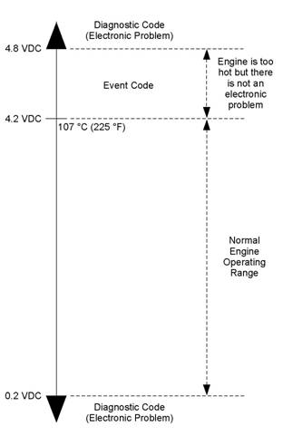
![]()
![]() KENR6224
KENR6224
51
Troubleshooting Section
Troubleshoot ing
Diagnosti c Code
Flash Codes
with
a
i02559723
Refer to the Troubleshooting Guide, “Diagnostic
Code Cross Reference” for the complete list of the
diagnostic codes and a description of each code.
There is a troubleshooting procedure for every
diagnostic code. Refer to the Troubleshooting Guide,
“Troubleshooting With A Diagnostic Code”.
When a diagnostic code is activated, the Electronic
Control Module (ECM) transmits information about
the code over the J 1939 data link. Some J1939
dev ices may display the code. However, the code will
Flash codes are a simple way to alert the operator
that a fault exists with the control system for the
engine or with the operation of the engine. Each
flash code is a two digit number. The diagnostic lamp
flashes in order to identify the flash code.
EXAMPLE
Note: Flash Code 27 would flash on the diagnostic
lamp in the following manner:
• Two short flashes
• Hesitation
• Seven short flashes
For the descriptions of the flash codes, refer to
Troubleshooting, “Diagnostic Code Cross Reference”.
be displayed with a J 1939 Diagnostic Code. Refer to
the Troubleshooting Guide, “Diagnostic Code Cross
Reference” for a cross-reference between J1939
Diagnostic Code and diagnostic codes.
Do not confuse diagnostic codes with event codes.
Event codes alert the operator that an abnormal
operating condition such as low oil pressure or high
coolant temperature has been detected. Refer to
the Troubleshooting Guide, “Troubleshooting with
an Event Code” for additional information on event
codes.
Diagnostic
Codes
i02559725
Diagnostic Codes
Diagnostic codes alert the operator that a fault in
the elec tronic system has been detected. Diagnostic
codes also indicate the nature of the fault to the
service technician. The electronic service tool is
a software program that is designed to run on a
personal computer. Diagnostic codes may be viewed
on a personal computer that has the electronic
servic e tool s oftware. Diagnostic codes consist of
the component identifier (CID) and the failure mode
identifier (FMI).
Component Identifier (CID) – The CID is a number
with three or four digits. The CID indicates the
component that generated the code. For example,
the CID number 0001 identifies the fuel injector for
the number one cylinder.
Failure Mode Identifier (FMI) – The FMI is a two
digit code that indicates the type of failure.
Illustration 10
Output voltage from a typical analog temperature sens or
g01117578
![]() 52
52
Troubleshooting Section
KENR6224
Illustration 10 indicates the signal range for a typical
analog sens or. Diagnostic codes will be generated if
the sensor’s output signal is below 0.2 VDC or above
4.8 VDC.
Active Diagnostic Codes
Diagnostic
Reference
Code
Cross
i02558820
An active diagnostic code represents a fault in the
electronic control system. Correct the fault as soon
as possible.
When the ECM generates an active diagnostic code,
the “Active Alarm” indicator (“Engine Control Alarm
Status” on the electronic service tool) is activated
in order to alert the operator. If the condition that
generated the code is momentary, the message
disappears from the list of active diagnostic codes.
The diagnostic code becomes logged.
Logged Diagnostic Codes
When the ECM generates a diagnostic code, the
ECM logs the code in permanent memory. The
ECM has an internal diagnostic clock. Each ECM
will record the following information when a code is
generated:
• The hour of the first occurrence of the code
• The hour of the last occurrence of the code
• The number of occurrences of the code
This information is a valuable indicator for
troubleshooting intermittent faults.
A code is cleared from memory when one of the
following conditions occur:
• The service technician manually clears the code.
• The code does not rec ur for 100 hours.
• A new code is logged and there are already ten
codes in memory. In this case, the oldest code is
cleared.
Some diagnostic codes may be easily triggered.
Some diagnostic codes may log occurrences that did
not result in complaints. The most likely cause of an
intermittent fault is a faulty c onnection or damaged
wiring. The nex t likely cause is a c omponent failure.
The least likely cause is the failure of an electronic
module. Diagnostic codes that are logged repeatedly
may indicate a fault that needs special investigation.
Note: Always clear logged diagnostic codes after
investigating and correcting the fault which generated
the code.
Faults in the electronic control system are reported
via thes e types of codes: flash codes, CID/FMI
diagnostic codes, and event codes.
For information on flash codes, refer to
Troubleshooting, “Flash Codes”.
For information on CID/FMI codes, refer to
Troubleshooting, “Diagnostic Codes”.
For information on event c odes, refer to
Troubleshooting, “Event Codes”.
Use Table 10 as a cross-reference between the
various types of codes.
![]() KENR6224
KENR6224
53
Troubleshooting Section
Table 9
|
Cross Reference for Diagnostic Codes | |||
|
Flash Code |
CID(1)/FMI(2) Code |
J1939 Diagnostic Code |
Description of Diagnostic Code |
|
71 |
0001-11 |
J0651-11 |
Cylinder #1 Injector other failure mode |
|
72 |
0002-11 |
J0652-11 |
Cylinder #2 Injector other failure mode |
|
73 |
0003-11 |
J0653-11 |
Cylinder #3 Injector other failure mode |
|
74 |
0004-11 |
J0654-11 |
Cylinder #4 Injector other failure mode |
|
75 |
0005-11 |
J0655-11 |
Cylinder #5 Injector other failure mode |
|
76 |
0006-11 |
J0656-11 |
Cylinder #6 Injector other failure mode |
|
21 |
0041-03 |
J0678-3 |
8 Volt DC Supply voltage above normal |
|
21 |
0041-04 |
J0678-4 |
8 Volt DC Supply voltage below normal |
|
32 |
0091-08 |
J0091-8 |
Throttle Position Sensor abnormal fr equency, pulse width, or period |
|
24 |
0100-03 |
J0100-3 |
Engine Oil Pressure Sensor voltage above normal |
|
24 |
0100-04 |
J0100-4 |
Engine Oil Pressure Sensor voltage below normal |
|
27 |
0110-03 |
J0110-3 |
Engine Coolant Temperature Sensor voltage above normal |
|
27 |
0110-04 |
J0110-4 |
Engine Coolant Temperature Sensor voltage below normal |
|
51 |
0168-02 |
J0168-2 |
Electrical System Voltage erratic, intermittent, or incorrect |
|
38 |
0172-03 |
J0172-3 |
Intake Manifol d Air Temperature Sensor voltage above normal |
|
38 |
0172-04 |
J0172-4 |
Intake Manifold Air Temperature Sensor voltage belowe normal |
|
13 |
0174-03 |
J0174-3 |
Fuel Temperature Sensor voltage above normal |
|
13 |
0174-04 |
J0174-4 |
Fuel Temperature Sensor voltage below normal |
|
34 |
0190-02 |
J0190-2 |
Engine Speed Sensor erratic, intermittent, or incorrect |
|
34 |
0190-09 |
J0190-9 |
Engine Speed Sensor abnormal update rate |
|
34 |
0190-11 |
J0190-11 |
Engine Speed Sensor mechanical failure |
|
34 |
0190-12 |
J0190-12 |
Engine Speed Sensor failure |
|
58 |
0247-09 |
J0639-09 |
SAE J1939 Data Link abnormal update rate |
|
- |
0248-09 |
- |
Perkins Data Link not communicating |
|
- |
0253-02 |
- |
Personality Module erratic, intermittent, or incorrect |
|
- |
0254-12 |
- |
Electronic Control Module Error |
|
42 |
0261-13 |
J0637-13 |
Engine Timing Calibration calibration required |
|
21 |
0262-03 |
J0620-03 |
5 Volt Sensor DC Power Supply voltage above normal |
|
21 |
0262-04 |
J0620-04 |
5 Volt Sensor DC Power Supply voltage below nor mal |
|
56 |
0268-02 |
J0630-02 |
Programmed Parameter Fault erratic, intermittent, or incorrect |
|
25 |
0273-03 |
J0102-03 |
Turbocharger Outlet Pressure Sensor voltage above normal |
|
25 |
0273-04 |
J0102-04 |
Turbocharger Outlet Pressure Sensor voltage below normal |
|
26 |
0274-03 |
J0108-03 |
Atmospheric Pressure Sensor voltage above normal |
|
26 |
0274-04 |
J0108-04 |
Atmospheric Pressure Sensor voltage below normal |
|
34 |
0342-02 |
J0723-2 |
Secondary Engine Speed Sensor erratic, intermittent, or incorrect |
|
34 |
0342-11 |
J0723-11 |
Secondary Engine Speed Sensor other failure mode |
|
34 |
0342-12 |
J0723-12 |
Secondary Engine Speed Sensor failure |
(continued)
![]() 54
54
Troubleshooting Section
KENR6224
(Table 9, contd)
|
Cross Reference for Diagnostic Codes | |||
|
Flash Code |
CID(1)/FMI(2) Code |
J1939 Diagnostic Code |
Description of Diagnostic Code |
|
- |
0799-12 |
- |
Need Service tool update |
|
- |
1690-08 |
- |
Throttle #2 Position Sensor abnormal frequency, pulse width, or peri od |
(1)
(2)
Component Identifier
Failure Mode Identifier
Table 10
|
Cross Reference for Event Codes | |||
|
Flash Code |
Event Code |
J1939 Event Code |
Description of Event Code |
|
- |
E085 |
- |
Engine Shutdown Overridden |
|
- |
E162-1 |
J0102-15 |
High Boost Pressure (Warning) |
|
- |
E162-2 |
J0102-16 |
High Boost Pressure (Alert) |
|
- |
E255-1 |
- |
Diagnostic Reset |
|
46 |
E360-1 |
J0100-17 |
Low Engine Oil Pressure (Warning) |
|
46 |
E360-2 |
J0100-18 |
Low Engine Oil Pressure (Alert) |
|
46 |
E360-3 |
J0100-01 |
Low Engine Oil Pressure (Shutdown) |
|
61 |
E361-1 |
J0110-15 |
High Engine Coolant Temperature (Warning) |
|
61 |
E361-2 |
J0110-16 |
High Engine Coolant Temperature (Alert) |
|
61 |
E361-3 |
J0110-00 |
High Engine Coolant Temperature (Shutdown) |
|
35 |
E362-1 |
J0190-15 |
Engine Overspeed (Warning) |
|
35 |
E362-2 |
J0190-16 |
Engine Overspeed (Alert) |
|
35 |
E362-3 |
J0190-00 |
Engine Overspeed (Shutdown) |
|
65 |
E363-1 |
J0174-15 |
High Fuel Supply Temperature (Warning) |
|
65 |
E363-2 |
J0174-16 |
High Fuel Supply Temperature (Alert) |
|
- |
E368-1 |
J0172-15 |
High Intake Manifold Air Temperature (War ning) |
|
- |
E368-2 |
J0172-16 |
High Intake Manifold Ai r Temperature (Alert) |
CID
0001 FMI 11
i02559726
If the cause of the diagnostic code is a fault in the
common wire, two cylinders will be affected because
of the shared common wire for the electronic unit
injectors.
System Response:
Conditions Which Generate This Code:
The Electronic Control Module (ECM) is attempting to
operate the electronic unit injector. The ECM detects
an open circuit or a short circuit in the circuit for the
electronic unit injector.
The ECM will log the diagnostic code. The ECM will
continue to attempt to operate the electronic unit
injector after the code has been logged.
The electronic unit injector may not operate while the
condition exists.
![]() KENR6224
KENR6224
55
Troubleshooting Section
Possible Performance Effect:
• Engine misfires
• Low power
Perform the following diagnostic procedure: “Injector
Solenoid Circuit - Test”
Results:
• OK – STOP.
i02559727
CID 0002 FMI 11
Conditions Which Generate This Code:
The Electronic Control Module (ECM) is attempting
to operate the injec tor. The ECM detects an open
circuit or a short circuit in the circuit for the injector.
If the cause of the diagnostic code is a fault in the
common wire, two cylinders will be affected because
of the shared common wire for the injectors.
System Response:
The ECM will log the diagnostic code. The ECM will
continue to attempt to operate the injector after the
code has been logged.
The injector may not operate while the condition
exists.
Possible Performance Effect:
• Engine misfires
• Low power
Perform the following diagnostic procedure: “Injector
Solenoid Circuit - Test”
Results:
• OK – STOP.
i02559728
CID 0003 FMI 11
Conditions Which Generate This Code:
The Electronic Control Module (ECM) is attempting
to operate the injec tor. The ECM detects an open
circuit or a short circuit in the circuit for the injector.
If the cause of the diagnostic code is a fault in the
common wire, two cylinders will be affected because
of the shared common wire for the injectors.
System Response:
The ECM will log the diagnostic code. The ECM will
continue to attempt to operate the injector after the
code has been logged.
The injector may not operate while the condition
exists.
Possible Performance Effect:
• Engine misfires
• Low power
Perform the following diagnostic procedure: “Injector
Solenoid Circuit - Test”
Results:
• OK – STOP.
i02559729
CID 0004 FMI 11
Conditions Which Generate This Code:
The Electronic Control Module (ECM) is attempting to
operate the electronic unit injector. The ECM detects
an open circuit or a short circuit in the circuit for the
electronic unit injector.
If the cause of the diagnostic code is a fault in the
common wire, two cylinders will be affected because
of the shared common wire for the electronic unit
injectors.
System Response:
The ECM will log the diagnostic code. The ECM will
continue to attempt to operate the electronic unit
injector after the code has been logged.
The electronic unit injector may not operate while the
condition exists.
Possible Performance Effect:
• Engine misfires
• Low power
Perform the following diagnostic procedure: “Injector
Solenoid Circuit - Test”
![]() 56
56
Troubleshooting Section
KENR6224
Results:
• OK – STOP.
CID 0005 FMI 11
Conditions Which Generate This Code:
i02561040
If the cause of the diagnostic code is a fault in the
common wire, two cylinders will be affected because
of the shared common wire for the electronic unit
injectors.
System Response:
The ECM will log the diagnostic code. The ECM will
continue to attempt to operate the electronic unit
injector after the code has been logged.
The electronic unit injector may not operate while the
condition exists.
The Electronic Control Module (ECM) is attempting to
operate the electronic unit injector. The ECM detects
an open circuit or a short circuit in the circuit for the
electronic unit injector.
If the cause of the diagnostic code is a fault in the
common wire, two cylinders will be affected because
of the shared common wire for the electronic unit
injectors.
System Response:
The ECM will log the diagnostic code. The ECM will
continue to attempt to operate the electronic unit
injector after the code has been logged.
The electronic unit injector may not operate while the
condition exists.
Possible Performance Effect:
• Engine misfires
• Low power
Perform the following diagnostic procedure: “Injector
Solenoid Circuit - Test”
Results:
• OK – STOP.
i02561042
CID 0006 FMI 11
Conditions Which Generate This Code:
The Electronic Control Module (ECM) is attempting to
operate the electronic unit injector. The ECM detects
an open circuit or a short circuit in the circuit for the
electronic unit injector.
Possible Performance Effect:
• Engine misfires
• Low power
Perform the following diagnostic procedure: “Injector
Solenoid Circuit - Test”
Results:
• OK – STOP.
i02559721
CID 0041 FMI 03
Conditions Which Generate This Code:
The voltage level of the 8 volt supply is above normal.
System Response:
The Electronic Control Module (ECM) will log the
diagnostic code. The diagnostic code can be viewed
on a display module or on the electronic service tool.
The ECM flags all digital sensors as invalid data and
all digital sensors are set to the respective default
values.
Possible Performance Effect:
• The engine may experience low power.
Troubleshooting:
Perform the following diagnostic procedure: “Digital
Sensor Supply Circuit - Test”
Results:
• OK – STOP.
![]() KENR6224
KENR6224
57
Troubleshooting Section
CID
0041 FMI 04
i02559722
CID
0100 FMI
03
i02561050
Conditions Which Generate This Code:
The output voltage of the 8 volt supply falls below 7.5
VDC for at least two seconds.
System Response:
The Electronic Control Module (ECM) will log the
diagnostic code. The diagnostic code can be viewed
on a display module or on the electronic service tool.
The ECM flags all digital sensors as invalid data and
all digital sensors are set to the respective default
values.
Possible Performance Effect:
• Low power
Troubleshooting:
Perform the following diagnostic procedure: “Digital
Sensor Supply Circuit - Test”
Results:
• OK – STOP.
i02561043
CID 0091 FMI 08
Conditions Which Generate This Code:
The Electronic Control Module (ECM) detects an
incorrect frequency on the throttle signal.
System Response:
The code is logged. The ECM flags the throttle
position as invalid data and a default value of zero
percent is used.
Possible Performance Effect:
• The engine speed changes to the default selected
speed of 1500 rpm or 1800 rpm.
Troubleshooting:
Perform the following diagnostic procedure: “Throttle
Position Sensor Circuit - Test”
Results:
• OK – STOP.
Conditions Which Generate This Code:
The Electronic Control Module (ECM) detects a
signal voltage that is above normal.
System Response:
The code is logged. The ECM flags oil pressure as
invalid data and a default value is used.
Possible Performance Effect:
• There are no performance effects.
Troubleshooting:
Perform the following diagnostic procedure: “Engine
Pressure Sensor Open or Short Circ uit - Test”
Results:
• OK – STOP.
i02561052
CID 0100 FMI 04
Conditions Which Generate This Code:
The Electronic Control Module (ECM) detects a
signal v oltage that is below normal.
System Response:
The code is logged. The ECM flags oil pressure as
invalid data and a default value is used.
Possible Performance Effect:
• There are no performance effects.
Troubleshooting:
Perform the following diagnostic procedure: “Engine
Pressure Sensor Open or Short Circ uit - Test”
Results:
• OK – STOP.
![]() 58
58
Troubleshooting Section
KENR6224
CID
0110 FMI 03
i02561114
The signal voltage from the engine coolant
temperature sensor is less than 0.2 VDC for more
than eight seconds.
System Response:
Conditions Which Generate This Code:
The Electronic Control Module (ECM) detects the
following c onditions:
• The engine has been running for more than seven
minutes.
• The signal voltage from the engine coolant
temperature sensor is greater than 4.95 VDC for
more than eight seconds.
System Response:
The ECM will log the diagnostic code if the engine
has been running for more than seven minutes. The
check engine lamp will illuminate after a delay.
The ECM will set the value of the coolant temperature
to a default value.
The engine will not go into cold mode while this
diagnostic c ode is active.
The ECM will activate the cooling fan after this code
has been active for more than eight seconds.
Possible Performance Effect:
None
Troubleshooting:
Perform the following diagnostic procedure: “Engine
Temperature Sensor Open or Short Circuit - Test”
Results:
• OK – STOP.
i02561126
CID 0110 FMI 04
Conditions Which Generate This Code:
The Electronic Control Module (ECM) detects the
following c onditions:
The engine has been running for more than seven
minutes.
The ECM will log the diagnostic code. The check
engine lamp will illuminate after a delay.
The ECM will set the value of the coolant temperature
to a default value.
The engine will not go into cold mode while the
diagnostic code is active.
The ECM will activate the cooling fan after this code
has been active for more than eight seconds.
Troubleshooting:
Perform the following diagnostic procedure: “Engine
Temperature Sensor Open or Short Circuit - Test”
Results:
• OK – STOP.
i02561134
CID 0168 FMI 02
Conditions Which Generate This Code:
While the engine is running, the battery voltage drops
below 9 VDC intermittently, or the battery voltage
drops below 9 VDC three times in a seven second
period.
System Response:
The Electronic Control Module (ECM) will log the
diagnostic code.
Possible Performance Effect:
• The engine may misfire and/or shutdown
Troubleshooting:
Perform the following diagnostic procedure:
“Electrical Power Supply Circuit - Test”
Results:
• OK – STOP.
![]() KENR6224
KENR6224
59
Troubleshooting Section
CID
0172 FMI 03
i02562200
Results:
• OK – STOP.
Conditions Which Generate This Code:
The engine coolant temperature is above −10 °C
(14 °F). The signal voltage from the inlet manifold
air temperature sensor is greater than 4.95 VDC for
CID
0174 FMI
03
i02562205
more than eight seconds.
System Response:
The Electronic Control Module (ECM) will log the
diagnostic c ode. The ECM flags the inlet manifold
air temperature as invalid data and a default value
of 40 °C (104 °F) is used.
Possible Performance Effect:
None
Troubleshooting:
Perform the following diagnostic procedure: “Engine
Temperature Sensor Open or Short Circuit - Test”
Results:
• OK – STOP.
i02562201
CID 0172 FMI 04
Conditions Which Generate This Code:
The signal voltage from the inlet manifold temperature
sensor is less than 0.2 VDC for more than eight
seconds.
System Response:
The code is logged. The ECM will flag the inlet
manifold temperature as invalid data and the inlet
manifold temperature is set to a default value of
40 °C (104 °F).
Possible Performance Effect:
None
Troubleshooting:
Perform the following diagnostic procedure: “Engine
Temperature Sensor Open or Short Circuit - Tes t”
Conditions Which Generate This Code:
The Electronic Control Module (ECM) detects a
signal voltage that is above normal.
System Response:
The code is logged. The ECM flags the fuel
temperature as invalid data and a default value of
50 °C (122 °F) is used.
Possible Performance Effect:
• Low power
Troubleshooting:
Perform the following diagnostic procedure: “Engine
Temperature Sensor Open or Short Circuit - Test”
Results:
• OK – STOP.
i02562207
CID 0174 FMI 04
Conditions Which Generate This Code:
The Electronic Control Module (ECM) detects a
signal voltage that is below normal.
System Response:
The code is logged. The ECM flags the fuel
temperature as invalid data and a default value of
50 °C (122 °F) is used.
Possible Performance Effect:
• Low power
Troubleshooting:
Perform the following diagnostic procedure: “Engine
Temperature Sensor Open or Short Circuit - Test”
![]() 60
60
Troubleshooting Section
KENR6224
Results:
• OK – STOP.
CID 0190 FMI 02
Conditions Which Generate This Code:
• The engine speed is greater than 120 rpm.
i02562214
System Response:
The Electronic Control Module (ECM) will log the
diagnostic code. If a valid signal is not received from
the crankshaft pos ition sensor, the ECM will default
to the camshaft position sensor.
Possible Performance Effect:
• Engine misfires
• Engine shutdown
Note: The engine will shut down only if the signals
from both the crankshaft position sensor and the
•
The pattern for the timing ring is erratic, intermittent
or incorrect for five seconds.
camshaft position sensor are abnormal.
Troubleshooting:
System Response:
The Electronic Control Module (ECM) will log the
diagnostic code. If a valid signal is not received from
the crankshaft position sensor, the ECM will default
to the camshaft position sensor.
Possible Performance Effect:
• Engine misfires
• Engine shutdown
Note: The engine will shut down only if the signals
from both the crankshaft position sensor and the
camshaft position sensor are abnormal.
Troubleshooting:
Perform the following diagnostic procedure: “Engine
Speed/Timing Sensor Circuit - Test”
Results:
• OK – STOP.
i02562216
CID 0190 FMI 09
Conditions Which Generate This Code:
• The engine speed is greater than 120 rpm.
• The pattern for the timing ring is abnormal for five
seconds.
Perform the following diagnostic procedure: “Engine
Speed/Timing Sensor Circuit - Test”
Results:
• OK – STOP.
i02562217
CID 0190 FMI 11
Conditions Which Generate This Code:
• The engine speed is greater than 120 rpm.
• The signal from one of the position sensors is
missing for five seconds.
System Response:
The Electronic Control Module (ECM) will log the
diagnostic code. If a valid signal is not received from
the crankshaft position sensor, the ECM will default
to the camshaft position sensor.
Possible Performance Effect:
• Engine misfires
• Engine shutdown
Note: The engine will shut down only if the signals
from both the crankshaft position sensor and the
camshaft position sensor are abnormal.
Troubleshooting:
Perform the following diagnostic procedure: “Engine
Speed/Timing Sensor Circuit - Test”
![]() KENR6224
KENR6224
61
Troubleshooting Section
Results:
• OK – STOP.
CID 0190 FMI 12
Conditions Which Generate This Code:
• The engine speed is greater than 120 rpm.
i02562218
Possible Performance Effect:
• The engine may not operate correctly and/or the
equipment may not have engine speed control.
Troubleshooting:
Perform the following diagnostic procedure: “CAN
Data Link Circuit - Test”
Results:
• OK – STOP.
•
The timing ring is damaged or one of the position
sensors is damaged.
CID
0248 FMI
09
i02562252
System Response:
The Electronic Control Module (ECM) will log the
diagnostic code. If a valid signal is not received from
the crankshaft position sensor, the ECM will default
to the camshaft position sensor.
Possible Performance Effect:
• Engine misfires
• Engine shutdown
Note: The engine will shut down only if the signals
from both the crankshaft position sensor and the
camshaft position sensor are abnormal.
Troubleshooting:
Perform the following diagnostic procedure: “Engine
Speed/Timing Sensor Circuit - Test”
Results:
• OK – STOP.
i02562250
CID 0247 FMI 09
Conditions Which Generate This Code:
The signal from the data link is noisy or intermittent.
System Response:
The Electronic Control Module (ECM) will log the
diagnostic code.
Possible Performance Effect:
None
Troubleshooting:
Perform the following diagnostic procedure: “Data
Link Circuit - Test”
Results:
• OK – STOP.
i02562259
CID 0253 FMI 02
Conditions Which Generate This Code:
The Electronic Control Module (ECM) has detected a
loss of communications with the J1939 data link.
Ensure that all flash files in the control system are
current.
System Response:
The ECM will log the diagnostic code.
Conditions Which Generate This Code:
The flash file that is used for replacement is for
a different engine family or for a different engine
application.
System Response:
The electronic service tool will not be able to clear
the code.
![]() 62
62
Troubleshooting Section
KENR6224
Possible Performance Effect:
• The fuel injection s ystem is disabled and the
engine will not start.
Troubleshooting:
Check the Part Number of the Flash File
A. Restore the electrical power to the Elec tronic
Control Module (ECM).
B. Verify that the part number for the flash file agrees
with the latest update that is available on PTMI.
Expected Result:
The c orrect flash file is ins talled in the ECM.
Results:
• OK – The correct flash file is installed in the ECM.
Repair: The engine will not start until the 0253-02
diagnostic code is cleared. Clearing this code
requires factory passwords.
Acquire factory passwords. Clear the 0253-02
diagnostic code. Return the engine to service.
STOP.
• Not OK – The correct flash file is not installed in
the ECM.
Repair: Flash program the ECM with the correct
flash file. Refer to the Troubleshooting Guide,
“Flash Programming”. Verify that the fault has been
eliminated.
STOP.
i02562261
CID 0254 FMI 12
Conditions Which Generate This Code:
There is an internal fault in the Electronic Control
Module (ECM).
System Response:
The ECM will log the diagnostic code.
Possible Performance Effect:
The engine may not operate correctly.
Troubleshooting:
Refer to the Troubleshooting Guide, “Replacing the
ECM”.
Results:
• OK – STOP.
i02562306
CID 0261 FMI 13
Conditions Which Generate This Code:
The timing has not been calibrated since the
Electronic Control Module (ECM) was installed or the
calibration is incorrect.
System Response:
The ECM will log the diagnostic code.
The ECM uses default timing.
Possible Performance Effect:
• Engine misfires
• Low power
• Reduced engine speed
• White exhaust smoke
• Increased exhaust emissions
Troubleshooting:
Perform the following diagnostic procedure: “Engine
Speed/Timing Sensor - Calibrate”
Results:
• OK – STOP.
i02562312
CID 0262 FMI 03
Conditions Which Generate This Code:
The voltage level of the 5 volt supply is greater than
5.16 VDC for more than one second.
![]() KENR6224
KENR6224
63
Troubleshooting Section
System Response:
The code is logged. The ECM sets all of the pressure
sensors to the respec tive default values.
Possible Performance Effect:
Engine power is reduced.
Troubleshooting:
Perform the following diagnostic procedure: “5 Volt
Engine Pressure Sensor Supply Circuit - Test”
Results:
• OK – STOP.
i02562342
CID 0262 FMI 04
Possible Performance Effect:
Engine performance may be affected by the
unprogrammed parameters. The ECM may use a
default torque map or the ECM may limit the engine
to low idle.
Troubleshooting:
Program the system configuration parameters. Refer
to the Troubleshooting Guide, “System Configuration
Parameters” for additional information.
Results:
• OK – STOP.
i02561079
CID 0273 FMI 03
Conditions Which Generate This Code:
The voltage level of the 5 volt supply is less than 4.84
VDC for more than one second.
System Response:
The code is logged. The ECM sets all of the pressure
sensors to the respective default values.
Possible Performance Effect:
Engine power is reduced.
Troubleshooting:
Perform the following diagnostic procedure: “5 Volt
Engine Pressure Sensor Supply Circuit - Test”
Results:
• OK – STOP.
Conditions Which Generate This Code:
The signal voltage from the inlet manifold pressure
sensor is above normal.
System Response:
The Electronic Control Module (ECM) will log the
diagnostic code. The ECM will flag the inlet manifold
pressure as invalid data and a default value is used.
Possible Performance Effect:
• The engine may experience low power.
Troubleshooting:
Perform the following diagnostic procedure: “Engine
Pressure Sensor Open or Short Circ uit - Test”
Results:
• OK – STOP.
CID
0268 FMI 02
i02562385
CID
0273 FMI
04
i02561110
Conditions Which Generate This Code:
One or more of the programmable parameters have
not been programmed.
System Response:
The Electronic Control Module (ECM) will activate
the diagnostic code.
Conditions Which Generate This Code:
The signal voltage from the inlet manifold pressure
sensor is below normal.
![]() 64
64
Troubleshooting Section
KENR6224
System Response:
The Electronic Control Module (ECM) will log the
diagnostic code. The ECM will flag the inlet manifold
pressure as invalid data and a default value is used.
Possible Performance Effect:
• The engine may experience low power.
Troubleshooting:
Perform the following diagnostic procedure: “Engine
Pressure Sensor Open or Short Circuit - Test”
Results:
• OK – STOP.
i02562416
CID 0274 FMI 03
System Response:
The Electronic Control Module (ECM) will log
the diagnostic code. The ECM flags atmospheric
pressure as invalid data and a default value of
100 kPa (14.5 psi) is used.
Possible Performance Effect:
• Low power
Troubleshooting:
Perform the following diagnostic procedure: “Engine
Pressure Sensor Open or Short Circ uit - Test”
Results:
• OK – STOP.
i02563042
CID 0342 FMI 02
Conditions Which Generate This Code:
The signal voltage from the atmos pheric pressure
sensor is above 4.8 VDC for at least eight seconds.
System Response:
The Electronic Control Module (ECM) will log
the diagnostic code. The ECM flags atmospheric
pressure as invalid data and a default value of
100 kPa (15 psi) is used.
Possible Performance Effect:
Low power
Troubleshooting:
Perform the following diagnostic procedure: “Engine
Pressure Sensor Open or Short Circuit - Test”
Results:
• OK – STOP.
i02562429
CID 0274 FMI 04
Conditions Which Generate This Code:
The signal voltage from the atmos pheric pressure
sensor is below 0.2 VDC for at least eight seconds.
Conditions Which Generate This Code:
The Electronic Control Module (ECM) detects the
following conditions:
• The engine speed is greater than 120 rpm.
• The pattern for the timing ring is erratic, intermittent
or incorrect for five seconds.
System Response:
The ECM will log the diagnostic code. The ECM
flags the signal from the camshaft position sensor as
invalid data and a default value of zero rpm is used.
Possible Performance Effect:
• Engine misfires
• Engine shutdown
Note: The engine will shut down only if signals from
both the crankshaft position s ensor and the c amshaft
pos ition sensor are abnormal.
Troubleshooting:
Perform the following diagnostic procedure: “Engine
Speed/Timing Sensor Circuit - Test”
Results:
• OK – STOP.
![]() KENR6224
KENR6224
65
Troubleshooting Section
CID
0342 FMI 11
i02563070
Possible Performance Effect:
• Engine misfires
• Engine shutdown
Conditions Which Generate This Code:
The Electronic Control Module (ECM) detects the
following c onditions:
• The engine speed is greater than 120 rpm.
• The signal from the camshaft position sensor is
missing for five seconds.
System Response:
The ECM will log the diagnostic code. The ECM
flags the signal from the camshaft position sensor as
invalid data and a default value of zero rpm is used.
Possible Performance Effect:
• Engine misfires
• Engine shutdown
Note: The engine will shut down only if the signals
from both the crankshaft position sensor and the
camshaft position sens or are abnormal.
Troubleshooting:
Perform the following diagnostic procedure: “Engine
Speed/Timing Sensor Circuit - Test”
Results:
• OK – STOP.
i02563585
CID 0342 FMI 12
Conditions Which Generate This Code:
The Electronic Control Module (ECM) detects the
following c onditions:
• The engine speed is greater than 120 rpm.
• The timing ring or the c amshaft position sensor is
damaged.
System Response:
The ECM will log the diagnostic c ode. The ECM
flags the signal from the camshaft position sensor as
invalid data and a default value of zero rpm is used.
Note: The engine will shut down only if the signals
from both the crankshaft position sensor and the
camshaft position sensor are abnormal.
Troubleshooting:
Perform the following diagnostic procedure: “Engine
Speed/Timing Sensor Circuit - Test”
Results:
• OK – STOP.
i02563588
CID 0799 FMI 12
Conditions Which Generate This Code:
The Electronic Control Module (ECM) detects the
following condition:
• The software for the electronic service tool is too
old.
System Response:
The electronic service tool will not display ev ery
diagnostic code or every event code.
Possible Performance Effect:
None
Troubleshooting:
Obtain the current version of the software for the
electronic service tool. Contact Perkins Engine
Company Limited for further information.
Results:
• OK – STOP.
![]() 66
66
Troubleshooting Section
KENR6224
CID
1690 FMI 08
i02563586
Conditions Which Generate This Code:
Although the signal from the analog throttle is within
the normal range of 0.5 Volts to 4.5 Volts, the signal
has an abnormal frequency, an abnormal pulse width
or an abnormal time period.
System Response:
The Electronic Control Module (ECM) will log the
diagnostic code.
Possible Performance Effect:
The engine speed changes to the default selected
speed of 1500 rpm or 1800 rpm.
Troubleshooting:
Perform the following diagnostic procedure: “Analog
Throttle Circuit - Test”
Results:
• OK – STOP.
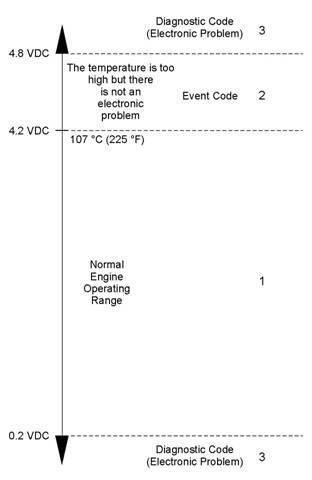
![]()
![]() KENR6224
KENR6224
67
Troubleshooting Section
Troubleshoot ing
Event Code
with
an
Event Codes
i02564763
Event codes alert the operator that an abnormal
engine operating condition such as low oil pressure or
high coolant temperature has been detected. When
the event code is generated, the event is active.
Active Event Codes
An active event code represents a fault with engine
operation. Correct the fault as soon as possible.
Active event codes are listed in ascending numerical
order. The code with the lowest number is listed first.
Illustration 11 is an example of the operating range of
a temperature sensor. Do not use the illustration to
troubleshoot temperature sensors.
Illustration 11
g01138880
Example of the typical operating range of a temperature sensor
(1) This area represents the normal operating range of the
parameter. The normal output voltage of the sensor is between
0.2 VDC and 4.2 VDC.
(2) In this area, the temperature above 107 °C (225 °F) is higher
than normal. The output voltage of the sensor will generate an
event code. The sensor does not have an electronic fault.
(3) In these areas, the output voltage of the sensor is too high
or too low. The voltage is outside of the normal range. The
elec tronic fault will generate a diagnostic code. Refer to
Troubleshooting, “Troubleshooting with a Diagnostic Code” for
additional information on diagnostic codes.
Events are represented in two formats. In the first
format, the “E” means that the code is an event
code. The “XXX” represents a numeric identifier for
the event code. This is followed by a description of
the code. If a warning, a derate, or a shutdown is
applicable, the numeric identifiers are different. Refer
to the following example:
• E004 Engine Overs peed Shutdown
In the second format, the “E” means that the
code is an event code. The “XXX-X” represents a
numeric identifier for the event code. The fourth “X”
identifies the event as a warning, an ac tion alert, or
a shutdown. This is followed by a description of the
code. Refer to the following example:
![]() 68
68
Troubleshooting Section
KENR6224
•
•
•
E360-1 Low Oil Pressure Warning
E360-2 Low Oil Pressure Action Alert
E360-3 Low Oil Pressure Shutdown
Troubleshooting
For basic troubleshooting of the engine, perform the
following steps in order to diagnose a fault:
1. Obtain the following information about the fault:
The definition for a warning, an action alert and a
shutdown are defined below:
Warning – This condition represents a serious fault
with engine operation. However, this c ondition does
not require an action alert or a s hutdown.
Action Alert – For this condition, the OEM control
panel may shut down the engine.
Shutdown – For this condition, the ECM should shut
down the engine.
Logged Event Codes
•
•
•
•
The event and the time of the event
Determine the conditions for the event. The
conditions will include the engine rpm and the
load.
Determine if there are any systems that were
installed by the dealer or by the customer that
could cause the event.
Determine whether any additional events
occurred.
When the ECM generates an event code, the ECM
logs the code in permanent memory. The ECM has
an internal diagnostic clock. The ECM will record
the following information when an event code is
generated:
• The hour of the first occurrence of the code
• The hour of the last occurrence of the code
• The number of occurrences of the code
Logged events are listed in chronological order. The
most recent event code is listed first.
This information can be helpful for troubleshooting
intermittent faults. Logged codes can als o be used to
review the performance of the engine.
Clearing Event Codes
2.
3.
4.
Verify that the fault is not due to normal engine
operation. Verify that the fault is not due to error of
the operator.
Narrow the probable cause. Consider the operator
information, the conditions of operation, and the
his tory of the engine.
Perform a visual inspection. Inspect the following
items:
• Fuel supply
• Oil level
• Oil supply
• Wiring
• Connectors
A code is cleared from memory when one of the
following conditions occur:
• The code does not recur for 100 hours.
• A new code is logged and there are already ten
codes in memory. In this case, the oldest code is
cleared.
• The service technician manually clears the code.
Always clear logged event codes after investigating
and correcting the fault which generated the code.
Be sure to check the connectors. This is very
important for faults that are intermittent. Refer to
Troubleshooting, “Electrical Connectors - Inspect”.
If these steps do not resolve the fault, identify the
procedures in this manual that best describe the
event. Check each probable cause according to the
tests that are recommended.
Trip Points for the Monitoring
System
The monitoring system determines the level of action
that is taken by the ECM in response to a condition
that can damage the engine. When any of these
conditions occur, the appropriate event code will trip.

![]() KENR6224
KENR6224
69
Troubleshooting Section
Table 11 contains the conditions that are monitored
and the default trip points for each condition.
Each condition has an associated parameter. The
settings for each parameter can be viewed with the
electronic service tool. The trip points for some of
the parameters may be adjustable with the electronic
service tool.
Table 11
Event Code
E162
-1
Parameter
High Boost Pressure
Warn Operator (1)
On
State
Trip Point
300 kPa (43.5 psi)
Delay Time
30 seconds
-2
E360
-1
-2
-3
E361
-1
-2
-3
E362
-1
-2
-3
E363
-1
-2
Acti on Alert (2)
Low Engine Oil Pressure
Warn Operator (1)
Acti on Alert (2)
Engine Shutdown (3)
High Engine Coolant Temperature
Warn Operator (1)
Acti on Alert (2)
Engine Shutdown (3)
Engine Overspeed
Warn Operator (1)
Acti on Alert (2)
Engine Shutdown (3)
High Fuel Supply Temperature
Warn Operator (1)
Acti on Alert (2)
Always On
On
Always On
Always On
On
Always On
Always On
On
Always On
Always On
On
Always On
None
300 kPa (43.5 psi)
None
None
104 °C (2190 °F)
105 °C (221 °F)
108 °C (226 °F)
2000 RPM
2050 RPM
2140 RPM
60 °C (140 °F)
68 °C (154 °F)
5 seconds
60 seconds
2 seconds
2 seconds
60 seconds
10 seconds
10 seconds
1 second
1 second
0 second
60 seconds
60 seconds
E368
-1
-2
High Engine Intake Manifold Air Temperature
Warn Operator (1) On
Acti on Alert (2) Always On
75 °C (167 °F)
78 °C (172 °F)
60 seconds
10 seconds
E162 High
Boost Pressure
i02564844
Possible Performance Effect:
E162-1 (Warning)
None
Conditions Which Generate This Code:
The Electronic Control Module (ECM) detects one of
the following conditions:
• Engine overload
System Response:
The event code will be logged.
E162-2 (Action Alert)
The engine may be shut down by the OEM control
panel.
Troubleshooting:
The engine may be overloaded.
Reduce the load on the engine.
![]() 70
70
Troubleshooting Section
KENR6224
Results:
• OK – STOP.
E360 Low Engine
i02564766
Oil Pressure
b. Oil pump gears that have too much wear will
cause a reduction in oil pressure. Repair the
engine oil pump.
C. The inlet screen of the oil suction tube for the
engine oil pump can have a restriction. This
restriction will cause cavitation and a loss of
engine oil pres sure. Check the inlet screen on
the oil pickup tube and remove any material that
may be restricting engine oil flow. Low engine oil
pressure may also be the result of the oil pickup
Conditions Which Generate This Code:
The Electronic Control Module (ECM) detects a, fault
with the engine oil pressure. Information on default
settings and ranges for this event can be found in
Troubleshooting, “Event Codes”.
System Response:
The event code will be logged.
Possible Performance Effect:
E360-1 (Warning)
None
E360-2 (Action Alert)
The engine may be shut down by the OEM control
panel.
E360-3 (Shutdown)
The engine will shut down.
Troubleshooting:
There may be a fault in the lubrication system for
the engine.
Check the Engine’s Lubrication System
A. Check the engine oil level. If the oil lev el is below
the s upply tube for the oil pump, the oil pump will
not have the ability to supply enough lubrication to
the engine components. If the engine oil level is
low, add engine oil in order to obtain the correct
engine oil level.
B. Check the following faults that may occur to the
engine oil pump:
a. Air leakage in the supply side of the oil pump
will also cause cavitation and loss of oil
pressure. Check the supply side of the oil pump
and make necessary repairs.
tube that is drawing in air. Check the joints of the
oil pickup tube for cracks or a damaged O-ring
seal.
D. If the engine oil bypass valves are held in the
open position, a reduction in the oil pressure can
be the result. This may be due to debris in the
engine oil. If the engine oil bypass valves are
stuck in the open position, remove each engine
oil bypass valve and clean each bypass valve in
order to correct this fault. You must also clean
each bypass valve bore.
E. Engine oil that is c ontaminated with fuel or coolant
will cause low engine oil pressure. High engine
oil level in the crankcase can be an indication of
contamination.
F. Excessive clearance at engine bearings will
cause low engine oil pres sure. Check the engine
components for excessive bearing clearance.
G. An oil line that is open, broken, or disconnected
will cause low engine oil pressure.
Expected Result:
An inspection of the lubrication system for the engine
indicated a fault.
Results:
• OK – There is a fault in the lubrication system for
the engine.
Repair: Repair the fault. Ensure that the repair
eliminates the fault.
STOP.
![]() KENR6224
KENR6224
71
Troubleshooting Section
E361
High
Engine
i02564767
Coolant
D. Check the water temperature regulator. A water
temperature regulator that does not open, or a
water temperature regulator that only opens part
of the way can cause overheating.
Temperature
Conditions Which Generate This Code:
The Electronic Control Module (ECM) detects a fault
in the engine cooling sy stem. Information on default
settings and ranges for this event can be found in
Troubleshooting, “Event Codes”.
System Response:
The event code will be logged.
Possible Performance Effect:
E361-1 (Warning)
• There are no performance effects.
E361-2 (Action Alert)
• The engine may be shut down by the OEM control
panel.
E361-3 (Shutdown)
• The engine will be shut down.
Troubleshooting:
There may be a fault in the engine cooling system.
Check the Engine’s Cooling System
A. Verify that the cooling sy stem is filled to the proper
lev el. If the coolant level is too low, air will get into
the cooling system. Air in the cooling system will
cause a reduction in coolant flow.
B. Check the radiator or the heat exchanger for a
restriction to coolant flow.
a. Check for debris or damage between the fins
of the radiator core. Debris between the fins of
the radiator core restricts air flow through the
radiator core.
b. Check internally for debris, dirt, or deposits on
the radiator core. Debris, dirt, or deposits will
restrict the flow of coolant through the radiator.
C. Check the concentration of the Extended Life
Coolant (ELC). Make sure that the coolant
mixture meets recommendations. Refer to the
Operation and Maintenance Manual, “Fluid
Recommendations”.
E. Check the water pump. A water pump with a
damaged impeller does not pump enough coolant.
Remove the water pump and check for damage
to the impeller.
F. If the cooling system for this application is
equipped with a fan, check the operation of the
fan. A fan that is not turning at the correct speed
can cause improper air speed across the radiator
core. The lack of proper air flow across the
radiator c ore can cause the coolant not to cool to
the proper temperature differential.
G. Check for air in the cooling system. Air can enter
the cooling s ystem in different ways. The most
common causes of air in the cooling system are
the incorrect filling of the cooling system and
combustion gas leakage into the cooling system.
Combustion gas can get into the system through
inside cracks, a damaged cylinder head, or a
damaged cylinder head gasket.
H. Check the cooling system hoses and clamps.
Damaged hoses with leaks can normally be seen.
Hoses that have no visual leaks can soften during
operation. The soft areas of the hose can become
kink ed or crushed during operation. These areas
of the hose can restrict the coolant flow. Hoses
become soft and/or get cracks after a period of
time. The inside of a hose can deteriorate, and the
loose particles of the hos e can restrict the coolant
flow.
I. If the cooling system for this application is
equipped with an expansion tank, check the s hunt
line for the expansion tank. The shunt line must be
submerged in the expansion tank. A res triction of
the shunt line from the expansion tank to the inlet
of the jacket water pump will c ause a reduction in
water pump efficiency. A reduction in water pump
efficiency will result in low coolant flow.
J. If the cooling system for this application
is equipped with an aftercooler, check the
aftercooler. A restriction of air flow through the air
to air aftercooler c an cause overheating. Check
for debris or deposits which would prevent the free
flow of air through the aftercooler.
K. Check for a restriction in the air inlet system. A
restriction of the air that is coming into the engine
can cause high cylinder temperatures. High
cylinder temperatures cause higher than normal
temperatures in the cooling system.
L. Check for a restriction in the exhaust system.
A restriction of the air that is coming out of the
engine can c ause high cylinder temperatures.
![]() 72
72
Troubleshooting Section
KENR6224
M. Consider high ambient temperatures. When
ambient temperatures are too high for the rating
of the cooling system, there is not enough of a
temperature difference between the ambient air
and c oolant temperatures.
N. Consider high altitude operation. The cooling
capability of the cooling system is reduced at
higher altitudes. A pressurized cooling system that
is large enough to keep the coolant from boiling
must be used.
O. The engine may be running in the lug condition.
When the load that is applied to the engine is
too large, the engine will run in the lug condition.
When the engine is running in the lug condition,
engine rpm does not increase with an increase of
fuel. This lower engine rpm causes a reduction in
coolant flow through the s ystem.
Expected Result:
A thorough inspection of the cooling system revealed
a fault.
Results:
• OK – There is a fault in the cooling sy stem.
Repair: Repair the fault. Ensure that the repair
eliminates the fault.
STOP.
i02564769
E362 Engine Overspeed
Conditions Which Generate This Code:
The Electronic Control Module (ECM) detects an
overspeed condition. Information on default settings
and ranges for this event can be found in the
Troubleshooting Guide, “Event Codes”.
System Response:
The event code will be logged.
Possible Performance Effect:
E362-1 (Warning)
None
E362-2 (Action Alert)
The engine may be shut down by the OEM control
panel.
E362-3 (Shutdown)
The engine will be shut down.
Troubleshooting:
The operator may be operating the machine
incorrectly.
The governor gain may be set incorrectly.
Talk to the Operator
Determine the events that caused the overspeed of
the engine.
If necessary, adjust the gains on the governor.
Results:
• OK – STOP.
i02564853
E363 High Fuel Supply
Temperature
Conditions Which Generate This Code:
The temperature of the fuel has exceeded the trip
point. Information on default settings and ranges for
this event code can be found in the Troubleshooting
Guide, “Event Codes”.
System Response:
The event code is logged.
Possible Performance Effect:
E363-1 (Warning)
None
E363-2 (Action Alert)
The OEM control panel may shut down the engine.
Troubleshooting:
Check the Fuel System
Check the fuel system. If equipped, check the fuel
cooler.
![]() KENR6224
KENR6224
73
Troubleshooting Section
Expected Result:
A thorough inspection of the fuel s ystem revealed a
fault.
Results:
a.
Verify that the cooling system is filled to the
proper level. If the coolant level is too low,
air will get into the cooling system. Air in the
cooling system may cause cavitation. This will
cause a reduction in coolant flow which can
damage a cooling s ys tem.
•
OK
– There is a fault in the fuel system.
b. Check the quality of the coolant. Follow
the recommendations in the Operation and
Repair: Make the necessary repairs. Verify that
the repair eliminates the fault.
STOP.
i02565203
E368 High Intake Manifold Air
Temperature
c.
Maintenance Manual.
Check for adequate coolant flow through
the radiator. Check the inlet temperature of
the coolant at the radiator inlet. Compare
the reading to the regulated temperature.
If the temperature is OK, c heck the outlet
temperature of the coolant at the radiator
outlet. A high temperature differential indicates
an insufficient flow rate.
Conditions Which Generate This Code:
The Electronic Control Module (ECM) detects a fault
in the inlet manifold air temperature. Information on
default settings and ranges for this event can be
found in the Troubleshooting Guide, “Event Codes ”.
System Response:
The event code will be logged.
Possible Performance Effect:
E368-1 (Warning)
None
E368-2 (Action Alert)
The OEM control panel may shut down the engine.
Troubleshooting:
Inlet manifold air temperature can be high for the
following reasons:
• Engine cooling system
• High ambient air temperature
• High inlet air restriction and/or high altitude
• Restriction in the exhaust system
• Faulty inlet manifold temperature sensor and/or
circuit
Perform the following Inspect ions
A. Check for Cooling System Faults
d. Check for air in the cooling system. Air can
enter the cooling system in different ways . The
most common causes of air in the cooling
system are the incorrect filling of the cooling
system and combustion gas leakage into
the cooling system. Combustion gas can get
into the system through a cracked cylinder
liner, damaged cylinder liner seals, a crac ked
cylinder head, or a damaged c ylinder head
gasket.
e. Check the cooling system hoses and clamps.
Damaged hoses with leak s can normally be
seen. Hoses that have no visual leaks can
soften during operation. The soft areas of the
hose can become kinked during operation.
These areas can also collapse during
operation. These areas of the hose can restrict
the coolant flow. Hoses become soft and/or get
cracks after a period of time. The inside of a
hose can deteriorate, and the loose particles of
the hose can restrict the coolant flow.
f. Check the water pump. A water pump with
a damaged impeller does not pump enough
coolant. Remove the water pump and check for
damage to the impeller.
g. Check the water temperature regulator. A water
temperature regulator that does not open, or a
water temperature regulator that only opens
part of the way can cause overheating.
h. If the cooling system is equipped with an
aftercooler, chec k the aftercooler. A restriction
of air flow through the air to air aftercooler can
cause overheating of the engine. Check for
debris or deposits which would prevent the free
flow of air through the aftercooler.
![]() 74
74
Troubleshooting Section
KENR6224
i.
The engine may be running exc essively in the
lug condition. When the load that is applied to
the engine is too large, the engine will run in
the lug condition. When the engine is running in
the lug condition, engine rpm does not increase
with an increase of fuel. This lower engine rpm
causes a reduction in coolant flow through the
system. The lug condition causes excess heat
from the increase in fuel consumption.
Expected Result:
A fault has been found in the cooling system and/or
the related engine systems.
Results:
• OK – A thorough inspection revealed a fault.
Repair: Repair the fault. Ensure that the repair
B. Check for High Ambient Air Temperature
a. Determine if the ambient air temperature
is within the design specifications for the
cooling system. When ambient temperatures
are too high for the rating of the cooling
system, there is not enough of a temperature
difference between the ambient air and coolant
temperatures.
b. Determine the cause of the high air
temperature. Correct the situation, when
possible.
C. Check for High Inlet Air Restriction and/or
High Altitude Operation
a. When inlet air pressure is low, the turbocharger
works harder in order to achieve the desired
inlet manifold pressure. This increases inlet air
temperature.
b. Measure the inlet air pressure while the engine
is operating under load. For specific data, refer
to the Technical Data Sheets for the engine.
c. Check for plugged air filters. Check for
obstructions to the air inlet. A restriction of
the air that enters the engine can c ause
high cylinder temperatures. High cylinder
temperatures cause higher than normal
temperatures in the cooling system.
d. Replace the air filters and/or remove the
obstruction from the air inlet.
e. Consider high altitude operation. The cooling
capability of the cooling system is reduced at
higher altitudes. A pres surized cooling system
that has been designed for the higher altitudes
must be used. Ensure that the engine is
configured for high altitude operation.
D. Check for Exhaust System Restriction
Check for a restriction in the exhaust system.
A restriction of the air that is coming out of the
engine can cause high cylinder temperatures.
eliminates the fault.
STOP.
![]() KENR6224
KENR6224
75
Troubleshooting Section
Diagnosti c
Tests
Functional
5
i02565206
Volt Engine Pressure Sensor
Supply
Circuit - Test
System Operation Description:
The Electronic Control Module (ECM) creates a
regulated voltage of 5.0 ± 0.2 VDC that is supplied
to terminal 1 of the harness connectors for these
sensors:
• Inlet manifold pressure sensor
• Atmospheric pressure sensor
• Engine oil pressure sensor
This procedure covers the following diagnostic codes :
• 262-03 5 Volt Sensor DC Power Supply voltage
above normal
• 262-04 5 Volt Sensor DC Power Supply voltage
below normal
A +5 V diagnostic code is probably caused by a short
circuit to ground or a short circuit to another voltage
source in the harness. The next likely cause is a faulty
sensor. The least likely cause is a fault in the ECM.
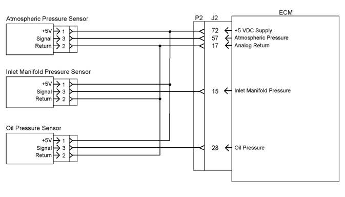
![]()
![]()
![]() 76
76
Troubleshooting Section
KENR6224
Illustration 12
Schematic for the 5 volt supply
Test Step 1. Inspect the
Electrical
g01284368
Connectors and the Wiring
A. Turn the keyswitch to the OFF position.
400-100-8969???15088860848
0574-26871589? 15267810868
0574-26886646? 15706865167
0574-26871569 18658287286